
Megasquirt (V3.57 board) - Tach input
|
|
Megasquirt (V3.57 board) - Tach input |
This page has now been superceded, please click here
Crank/primary tach input - Cam/secondary tach input
Crank/primary tach input
The V3.57 mainboard has two tach inputs available by internal selection.
 | Set mainboard for VR (true VR) |
 |
|
 | Set mainboard for VR input (with pullup) |
 | Set mainboard for Optoisolator input |
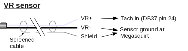
Tach input external connection

Tach input internal wiring (V3.57)

V3.57 board - VR Input for VR (magnetic) sensor
a) Find JP1 in the bottom right of the board. Place a jumper across positions 1 and 2
b) Find J1 in the middle of the board. Place a jumper across positions 3 and 4
c) With a small screwdriver, turn the pots, R52 and R56, 7 turns anticlockwise (sometimes you may feel a "click" when the end position is reached, they can't be damaged by turning too far.) This sets them up for most VR sensors.


V3.57 board - VR Input for logic input e.g. TFI, EDIS, GMDIS, LS1/24X, modules
a) Find JP1 in the bottom right of the board. Place a jumper across positions 1 and 2
b) Find J1 in the middle of the board. Place a jumper across positions 3 and 4
c) With a small screwdriver, turn the pots, R52 and R56, 7 turns anticlockwise (sometimes you may feel a "click" when the end position is reached, they can't be damaged by turning too far.)
d)Turn R56 back about 2 turns clockwise.
V3.57 board - VR Input with pullup for hall sensors, LS2/58X, optical sensors or points
a) Find JP1 in the bottom right of the board. Place a jumper across positions 1 and 2
b) Find J1 in the middle of the board. Place a jumper across positions 3 and 4
c) Install a 1k resistor (any value 470R - 2k2 is likely ok) onto the pads marked R57
d) With a small screwdriver, turn the pots, R52 and R56, 7 turns anticlockwise (sometimes you may feel a "click" when the end position is reached, they can't be damaged by turning too far.) and then turn R56 back about 2 turns clockwise.
V3.57 Opto-isolator (for coil negative fuel-only triggering):
a) Find JP1 in the bottom right of the board. Place a jumper across positions 2 and 3
b) Find J1 in the middle of the board. Place a jumper across positions 1 and 2
c) Place a jumper from XG1 to XG2 (just to the left of J1 above U3.) In exceptionally noisy situations it might be required to remove that jumper and instead runs XG1 out through a spare connection on the DB37 and through the loom direct to the engine.


Cam/secondary tach input
For Megasquirt-3 installs, the MS3X card is available to give sequential fuel and spark outputs and offers a second universal/VR tach input for a cam.
See 'MS3X cam.'
This is the recommended tach input method with Megasquirt-3.
Without the MS3X card a second input is possible with two main methods -
MS3X card - Cam Input

For hall or optical sensor inputs.
a) Install the jumper across JP7
b) Turn both pots (R11 and R32) 7 turns anti-clockwise (sometimes you may feel a "click" when the end position is reached, they can't be damaged by turning too far.)
c) Then turn the top one (R11) 3 turns clockwise.
For LS1 type sensor or logic modules inputs
a) Ensure JP7 is not jumpered.
b) Turn both pots (R11 and R32) 7 turns anticlockwise (sometimes you may feel a "click" when the end position is reached, they can't be damaged by turning too far.)
c) Then turn the top one (R11) 3 turns clockwise.
For a VR (magnetic) sensor input
a) Ensure JP7 is not jumpered.
b) Turn both pots (R11 and R32) 7 turns anti-clockwise (sometimes you may feel a "click" when the end position is reached, they can't be damaged by turning too far.)
Megasquirt-3 with MS3X - tach input external wiring

Spare Opto-isolator for cam input
When using the Universal/VR circuit for the main tach input and a hall-effect type sensor on the cam, it is possible to use the opto-isolator circuit on the mainboard for the cam input.

DIY VR circuit for cam
One option for conditioning a VR sensor on the cam is to build an LM1815 circuit.
You get to choose where the input comes from - a spare connection on the main connector.
The output must go to 'JS10'.

If you have a question, comment, or
suggestion for this FAQ please post it on the forum.
No part of this manual may be reproduced or changed without written permission from James Murray, Ken Culver and Philip Ringwood.