![]()
MS1-Extra Ignition Hardware manual
Only for use with the MS1 Extra code (MS1 - 68H908 based microprocessors)
By Philip Ringwood (daxtojeiro), James Murray (jsmcortina) and Ken Culver (muythaibxr)
|
MS1-Extra Ignition Hardware manual Only for use with the MS1 Extra code (MS1 - 68H908 based microprocessors) By Philip Ringwood (daxtojeiro), James Murray (jsmcortina) and Ken Culver (muythaibxr) |
|
Before you start any hardware mods please read this entire manual and the Software Manual, available HERE. |
Warning
for
E-Bay buyers!! Please see the Official Suppliers list before buying through E-Bay. This is there for your protection. |
|
Please Note:
All of these instructions / diagrams are to be used at your own risk, like most things there is more than one way to do the same thing, what we have tried to do is to offer a method that we have tested or that others have tested for us. No warranty expressed or implied. Use at your own risk. |
Select the Ignition Setup Option for your vehicle. Next select the Trigger Input Option (depending on what Version of MS PCB you have) for the trigger type that's fitted to your engine. Then select the Spark Output Option for your setup.
Layout of MS PCB's for V2.2 -- for V3.0 -- for V3.57
Component Schematics -- List of Component Part Numbers
Distributor Based Single coil Setup (MSnS) -- Neon/420A Decoder -- Wheel Decoder
Ford EDIS Ignition System -- Ford TFI Ignition --GM 7pin HEI ignition -- GM DIS Ignition -- Buick Computer Controlled Coil Ignition (C3I)
5 Cylinder Engines (Audi, etc) -- 4G63 powered DSM (Eclipse / Talon / Laser) -- SOHC Mitsubishi and Proton -- Rotary Engines -- Toyota VAST
Trigger Input Options for V2.2 PCBs (green pcb):
Hall or Optical input sensor wiring for V2.2 PCB -- VR input Sensor wiring for a V2.2 PCB -- Eliminating Cross Talk and Wiring Considerations for VR Sensors
Second VR Sensor Input for a V2.2 PCB -- Second Trigger Input
Luminition Optical Input for a V2.2 PCB -- Distributor points input for a V2.2 PCB
Trigger Input Options for V3.0 PCBs (blue pcb):
Hall or optical input sensor wiring for a V3.0 PCB -- VR input Sensor wiring for a V3.0 PCB -- Eliminating Cross Talk and Wiring Considerations for VR Sensors
Second VR Sensor Input for a V3.0 PCB -- Second Trigger Input
Luminition Optical Input for a V3.0 PCB -- Distributor points input for a V3.0 PCB
Spark Output Options for V2.2 PCB (green pcb):
MSD Amplifier (6A) output diagram for a V2.2 PCB -- Bosch Ignition Modules
Single Spark Coil Direct Drive Output from MS ECU for a V2.2 PCB
Two or more Spark Coils Direct Drive Output for a V2.2 PCB
Driving two coils from the same spark output e.g. wasted spark coil on plug (COP)
Spark Output Options for V3.0 PCB (blue pcb):
MSD Amplifier (6A) output diagram for a V3.0 PCB -- Bosch Ignition Modules
Single Spark Coil Direct Drive Output from MS ECU for a V3.0 PCB
Two Spark Coils Direct Drive Output for a V3.0 PCB -- Multiple Spark Coils Direct Drive Output for a V3.0 PCB
Driving two coils from the same spark output e.g. wasted spark coil on plug (COP)
Layout of the Megasquirt PCB's
V2.2 PCB:

Topside view of V2.2 pcb (these are green pcb's)
The V2.2 PCB has 4 spare connectors (X11 to X14) these can be used for various inputs and outputs for the following circuits as they are conveniently available on the 37pin DB connector:
X11 = pin 25 of 37pin db
X12 = pin 27 of 37pin db
X13 = pin 29 of 37pin db
X14 = pin 31 of 37pin db
The V3.0 PCB has 4 spare connectors (SPR1 to 4) these can be used for various inputs and outputs for the following circuits as they are conveniently available on the 37pin DB connector:
SPR1 = Pin3 of 37pin db
SPR2 = Pin4 of 37pin db
SPR3 = Pin5 of 37pin db
SPR4 = Pin6 of 37pin db
As can be seen, theres no proto area on the V3.57 and the components are very small. So soldering wires onto the board for spark outputs, hardware options, etc, is going to need a great deal of care. You may even have to remove some parts, which is not easily done to surface mount components, so I don't feel these manuals should cover doing this, as damage is very easy to do. Also a daughter board will need to be built if you want some of the hardware options as theres no proto area to build on. I have therefore assumed if you bought a V3.57 that you will not be modifying it to use the hardware functions such as Tacho out, PWM Idle valves, Boost control, Launch input, etc, etc. If you do wish to use these then you will have to build a daughter board of some form to mount the components on. If you use more than 2 spark outputs youll need to use the db15 connector, but ensure you strengthen the traces on the board with copper wire or solder to the pin directly, also connect the outputs in pairs of pins, as per the instructions HERE.
Note that the JS0 - JS11 pads are all electrically the same as the V3.0 PCB as are the SPR1 - 4 pads, so they can be used in the same way as the V3.0 PCB. The addition is JS12 which is the same as the bottom of R1 on the V3.0 pcb, but R1 will still need to be removed to use it on the V3.57, so be very very carefull !!!

Suggested points for Supplies inside the V3.0 ECU


List of component part numbers used in the ignition section:
|
DigiKey
part numbers:
|
Farnell
part numbers
|
|
2N2222A = 497-2598-5-ND |
2N2222A = 920-7120 |
Please note: Above part numbers will need checking, some components will come with a minimum order in multiples of 5 and 10.
More specific details on MSnS setups (Distributor based)

Ensure only LED17 (D14) is set as a spark output (Spark OutputA) there must be NO other Spark Outputs selected!!!
This mode is for use with a single coil distributor allowing
you to control your timing if you have a single coil firing
through a distributor, an MSD 6A amplifier, etc.
Your tach signal into the Megasquirt can come from a crank trigger or from
a "locked" distributor (dizzy) using hall, points, inductive VR
or opto sensors.
This mode requires ONE Trigger per Spark Event,
e.g. 2 pulses from a crank on a 4cy or 4 pulses from the disrtibutor
on a 4cy (distributor runs at half the speed of the crank) , 4 pulses
from the crank on a V8 or 8 from the distributor on a V8, etc.
If your engine has a toothed wheel (e.g. a 60-2, 24/2, 36-1, etc) then you
must NOT use MSnS mode, setup the WHEEL
DECODER MODE instead, and select SparkA as the only spark
output whilst using the distributor.
A locked distributor is one that has mechanical and vacuum advance either
removed or "locked" out so that the trigger signal occurs at the
same crankshaft angle at all rpms. Many distributor cars with EFI already
have a locked distributor.
Crank triggering provides a more stable advance as there is no timing chain
or belt and distributor gear jitter. For a four cylinder engine you would
require two pips/lobes or bolt heads (giving 2 signal pulses) at 180 degrees
to each other and a VR / hall sensor, for a 6cy you will need 3 pulses per
crank revolution at 120deg intervals and 4 for a V8 at 90deg intervals.
(note that a crank rotates at half the speed of the cam drive). The V3 circuit
board can directly read from a VR sensor. The V3 board also provides a VB921
high current driver that will drive your single coil directly, this means
you dont need an amplifier/dwell controller. If you use a crank trigger
you do not need to modify your distributor. Just make sure that the internal
rotor points towards one of the towers when the engine is roughly in the
firing angle - if it is halfway you can easily get cross-firing between
cylinders.
Below is a general layout drawing of the V3.0 MS ECU and trigger sensor with the coil.

IMPORTANT - do NOT set your total Trigger Angle (i.e. Trigger
Angle plus additions) inbetween the range 20 to 50 degrees as you will encounter
problems and be unable to get your desired advance. If this is the Trigger
Angle you calculate then you either need to move your crank sensor/wheel
or modify your distributor to obtain a compatible trigger angle. This is
due to the way the ECU calculates the spark timing, the calculations need
around a 5deg band from the Trigger Angle.
e.g. If you set a Trigger Angle of 23 degrees (no additions) then your maximum
advance would be about 18degrees which will almost certainly give you a
very lame engine down on power.
If the Trigger Angle setting is less than 15 deg the code will use "Next
Cylinder" sparking, which means it will work out the timing for the
next spark rather than the current spark, this is perfectly acceptable.
Please note: VR sensor users must use "Time Based cranking" when in MSnS mode, this is in the Spark Settings page.
Hall sensor users can take advantage of "Trigger Return" In this mode the trigger should be active (5V - 12V) at least 5-10 degrees before maximum advance and stay active until 5-0 degrees BTDC. The trigger going low (0V) sets off the spark when cranking. This will give accurate advance during the uneven cranking period. The middle LED (LED18 - D15) on the front panel (When set to "IRQ TRIGGER" in the Codebase and Output functions) shows the current status of the trigger to make it easier to adjust the distributor, or whatever triggers the MS. LED on = trigger high, LED off = trigger low. This LED is only of real use for hall sensors and needs to be configured in TunerStudio. On "Codebase and Outputs function" set LED18 (D15) to IRQ trigger.
Hall sensor in Distributor setup
How you should connect a Hall sensor to the Megasquirt all depends on what
comes out of the Hall sensor.
1)Turn the engine until cylinder 1 is at approx 25 Deg BTDC.
2)Turn the distributor until the rotor points in the middle
of the contact for cylinder 1 in the distributor cap.
Sometimes you may need to "re-phase" your distributor to change
the angular relationship between the rotor arm and the vanes if using a
trigger inside it.
3)Make sure one of the metal finger edges are close to the
Hall sensor if using the distributor sensor to fire the MS, if your using
a crank sensor then ensure this is near an edge of one of the lugs of the
crank wheel.
Confirm the crankshaft angle - either using timing tape or
by estimating. For correct code operation you need a vane edge either in
the distributor or on the crank if using a crank sensor, to pass the trigger
when the engine is at 60-90BTDC OR 5-15BTDC. If it passes at 16-50BTDC you
MUST re-phase you distributor or move the crank sensor round or you
will be unable to set your advance correctly.
If modification is required, typically set the vane edge to pass the sensor
when the engine is at 60BTDC and have the rotor arm pointing directly to
the tower when the engine is at 25BTDC.
Turn the engine backwards until the edge is well out of the Hall sensor. Measure the output voltage from the Hall sensor Turn the engine forward until the edge has passed through the Hall sensor. Measure the output voltage.
If both voltages are low, attach a 1K pullup resistor (see HERE for a pullup diagram) to the output wire of the hall sensor. Test again.
For a V3 PCB connect the input as the Hall Sensor Input diagram (see HERE)
For a V2.2 PCB : If the output goes from high to low
you should use the Hi to Lo schematic HERE
If the output goes from low to high you should use the Lo to Hi schematic
HERE
A distributor is needed with the MSnS mode to distribute the spark the correct cylinder, since it only has one ignition output. If the distributor is used to trigger the ignition all advance mechanisms have to be locked.
The distributor may have to be modified to ensure that the
spark is delivered to the correct cylinder. The only important thing is
that the rotor arm points to the correct contact in the distributor cap.
The best bet is to get the rotor arm line up to a contact at about 25 degrees
before TDC. It is not important to get exactly this angle, some 10 degrees
before or after will be probably be OK, as long there is no risk for cross
fire (spark on wrong cylinder)
Setup - Hall sensor
First, in TunerStudio in the Codebase and outputs function, set LED18
to "irq trigger" and send to ECU.
1) Set the crank at TDC
2) Rotate the distributor (opposite direction) just until middle LED turns
OFF (sets the crank angle)
3) Make sure the rotor arm points towards the correct contact in the distributor
cap
4) Fix the distributor
5) Turn engine backwards until middle LED turns ON (should be almost immediately)
and continue turning until it turns OFF again
6) Measure angle BTDC (+/- 10 degrees is good enough) at the crank
7) Enter measured angle in "Trigger angle"
8) Enter "Fixed angle" to 10 degrees
9) Start the engine
10) Adjust "Trigger angle" until the timing light is at 10 degrees
11) Set "Fixed angle" to -10
12) Start tuning
Setup - VR sensor
1) Set the crank at 20BTDC
3) Make sure the rotor arm points towards the correct contact in the distributor
cap
4) Bolt down the distributor
5) Turn engine backwards until the pip lines up with the VR sensor
6) Measure angle BTDC (+/- 10 degrees is good enough) at the crank
7) Enter measured angle in "Trigger angle" of Spark
Settings
8) Enter "Fixed angle" to 10 degrees this tells the ECU
to ignore the spark map and hold it to the Fixed Angle.
9) Start the engine
10) Adjust "Trigger angle" until the timing light is at
10 degrees
11) Set "Fixed angle" to -10 , this tells the ECU to run
from the spark map again.
12) Start tuning
Here is a list of links to a superb section on Distributor based setups, showing more detail that the above.
|
|
MS Connections |
TunerStudio Settings* |
|
||
|
||
|
||
|
||
Malory Unilite (optical trigger) |
||
|
||
|
||
|
*All of the above TunerStudio settings are for Next Cylinder Mode. See below for an explanation of Next/This cylinder mode
Wiring for the Neon / 420A Decoder -- Setting the Software for Neon/420A
Chrysler/Dodge/Plymouth
The "Neon/420A" mode theoretically supports the following vehicles
when equipped with a 2.0 or 2.4 4cylinder Chrysler engine.
"NS" body models:
1996-2000 Chrysler Town and Country
1996-2000 Dodge Caravan/Grand Caravan
1996-2000 Plymouth Voyager/Grand Voyager
"JA" body models:
1995-02 Chrysler Cirrus
1995-02 Dodge Stratus
1996-2000 Plymouth Breeze
"JX" body models:
1996-02 Chrysler Sebring Convertible
"PL" body models:
1995-02 Dodge Neon
1995-2001 Plymouth Neon
"PT" body models:
01-02 Chrysler PT Cruiser
"FJ" body models:
1995-02 Chrysler Sebring Coupe
1995-2000 Dodge Avenger
Wiring for the Neon / 420A Decoder
Circuit Diagram for V3.0 PCB:
Wire the Megasquirts ECU's input section up as per this diagram in the input wiring section:
Wire the Output Section like this:
Remove, if fitted, link between IGN and IGBTOUT
Circuit Diagram for V2.2 PCB:
Wire the Megasquirts ECU's input section up as per this diagram in the input wiring section:
Wire the Output Section like this:

Diagram for V2.2 and V3.0 wiring:
Next wire 2 x HEI 4 Pin Modules like this:
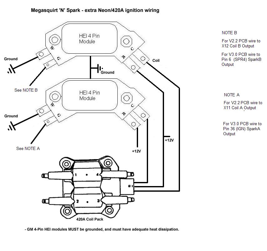
The wiring diagram attached shows the general wiring for a V2.2 or a V3.0 PCB Megasquirt, when installed on a 420A equipped Mitsubishi Eclipse / Eagle Talon.
Setting the Software for Neon/420A
In Ignition Options / Wheel Decoder and Output Pin Options ensire that NEON/420A is the only ignition option selected and that LED17 and LED19 are the ONLY 2 Spark outputs!!


Coil On Plug (COP) -- Where to mount the sensor and wheel -- Megasquirt hardware mods for 2 rotor with the NipponDenso -- Software Settings
The wheel decoder allows the use of a multi-toothed trigger
wheel such as 36-1 (commonly fitted to Fords), 60-2 (used mainly by Bosch
and therefore very widespread in Europe.) See www.trigger-wheels.com
for a supplier of custom made wheels. Other custom wheels such as 6-1 or
4-1 also work. Also supported are dual wheels such as the 24/2 wheels seen
on Mazdas and Toyotas. These have two wheels, one with 24 evenly spaced
teeth and a second pair of teeth with a second sensor. (See the Second Sensor
Input Section HERE)
The code supports:
Fuel only
Single coil (distributor based setup)
Wasted spark with multiple coils
It can also support coil per plug in some installs.
For wasted spark you require a minimum
of single "missing tooth" crank wheel, only engines with an even
number of cylinders being supported. You need at least 4-1 for 4cyl, 6-1
for 6cyl or 8-1 for 8cyl. However, the 36-1 wheel is probably the easiest
to obtain. The MS ECU can drive up to 6 seperate spark outputs, meaning
it can run up to a 12 cylinder in wasted spark mode. (4cy, 6cy, 8cy 10cy
and a 12cy)
Coil per plug can be achieved with a crank wheel and single-tooth cam wheel
OR a dual wheel cam setup OR a missing-tooth cam-wheel alone.
For a distributor based setup with a trigger wheel, simply follow all of the wheel decoder instructions but rather than setting SparkB, C, etc as outputs (as in a wasted spark setup) only set LED17 as SparkA output and ensure all other spark outs are NOT set:
LED17 (D14) = SparkA
LED18, LED19, Output3/SparkD, pin10 shift and knockin must NOT be a Spark output
The easiest install will be wasted spark using VB921 FET's to drive the spark coil(s) directly from a V3.0 PCB. (See the Spark Output selections available HERE) In this way it can be used like EDIS but without the need for an EDIS module, it has the advantage of allowing spark cut rev limiting. The downside is that it is more difficult than EDIS and requires extra software settings. If you are buying a pre-assembled Megasquirt your vendor will be able to do this for you.
The wheel decoder is a very powerful front end on top of the MSnS spark code that allows generic crank/cam angle wheels and vr sensors to be used with the Megasquirt for tach triggering, and ignition. Before setting up the wheel decoder, several questions should be asked:
1) How many cylinders (or rotors?) this will tell you how
often you get a firing event, and help with setup later.
8 cyl: 90 deg between firing
6 cyl/3 rotor: 120 deg between firing
4 cyl/2 rotor: 180 deg between firing
2) Where is your wheel going to be mounted, camshaft or crankshaft? This matters because the camshaft turns half a revolution for every crank revolution. This will also help determine how to set things up later.
3) Are you going to use a wheel with a missing tooth or a Cam Angle Sensor which actually has 2 wheels and 2 VR sensors.
4) Finally, how many teeth does your wheel(s) have?
5) When does the missing tooth (teeth) pass the sensor with respects to TDC or what tooth does the sensor see when the engine is at TDC?
When you have all this information, you're at least ready to start.
Where to mount the sensor and wheel
Lets asume your going to change a distributor based setup over to a wasted spark coil pack setup. The changes needed will be different for each engine but the basics should be the same: A wheel will need to be fitted on the crank pulley, a VR sensor will need to be mounted to detect the wheel and a set of coil packs will need to be mounted onto the car.
 Typical trigger discs (36-1) from a Ford
  VR Sensor
Mounting the wheel is quite critical in that it MUST be mounted so it rotates without moving up, down, left or right as the sensor needs to see all of the teeth with a gap of 0.75 - 1.0mm. The VR sensor can be found on virtually all Fords that have a coil pack under the bonnet, you'll need the coil pack too, so get them both at the same time, also keep the HT leads as the connectors will be needed. The VR sensor is usually mounted on the bell housing somewhere, depending on the engine.
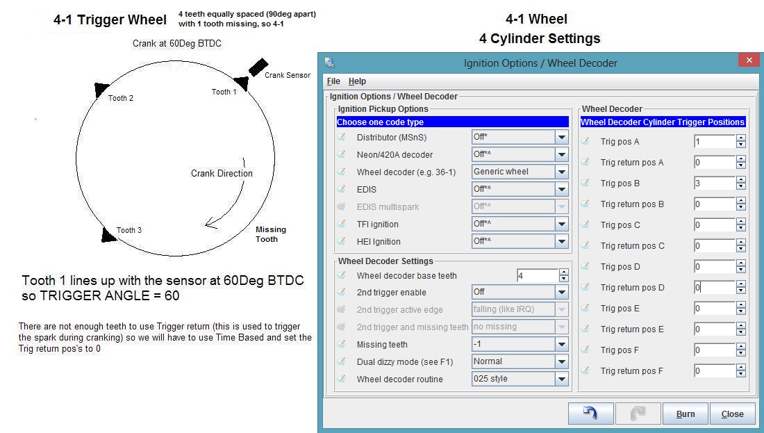
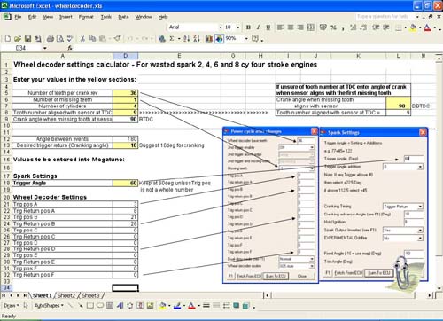
When fitting the wheel set the engine to Top Dead Centre (TDC) if you fit the sensor so it aligns with tooth 9, as the following diagram, then you can use the Trigger Wheel settings in the diagram, this is recommended for ease of setting up.
Set the Trigger Return Value to 60deg and Spark Inverted Output = YES in the Spark Settings Menu.

Megasquirt hardware mods for 2 rotor rotary engines with the NipponDenso 2 tooth/24 tooth cam angle sensor:
1) Solder some jumper wire to U4 (opto-isolator) pin 6.
2) Solder some jumper wire to CPU pin 11
3) build a dual lm1815 or dual v3 vr conditioner circuit. (covered elsewhere).
4) Wire the output of one of the vr conditioners to the jumper wire soldered
to U4 pin 6, and wire the other VR sensor output through a 1k resistor to
the cpu pin 11 jumper wire.
5) Connect the 24 tooth VR sensor positive lead to the VR+ input of whichever
circuit is connected to U4 pin 6, connect the other VR sensor positive lead
to the other conditioner circuit.
At this point, we're ready to talk about VR sensor alignment, etc...
Since we're on a 4 cylinder/2 rotor engine, and we're using
a CAM angle sensor, which moves half the speed of the crank, we really have
what looks like a 12+1 wheel to the megasquirt. So what we want to do is
figure out what advance the engine likes when it's starting. For rotaries...
0, or even -5 degrees is good,
I think most 4 cylinders should work well with 10 deg. This will help us
determine our trigger angle:
We want our first trigger to be the tooth directly after the second wheel's tooth passes by the VR sensor; that tooth will be labled "tooth 1". For a rotary, we want a max advance of maybe 40 deg BTDC at high revs and low kPa, and we want a cranking angle of 0 degrees. On a 12 tooth wheel, each tooth represents 30 degrees of crank rotation. Since we want a maximum advance of 40 degrees, a good value for the trigger angle would be 50 degrees. However, if we count the next two teeth over, we get 20 degrees, and -10 degrees. This won't work for our cranking angle, so we set the trigger angle to 60 degrees BTDC, so the next two teeth are 30 degrees and 0 degrees.
With this configuration, in the wheel decoder settings you'd want the following settings:
Trigger A: 1 (60 deg BTDC)
Trigger A Return: 3 (0 Deg for rotor 1)
Trigger B: 7 (180 degrees from trigger 1, or 90 degrees on the cam angle
sensor, 60 deg btdc for rotor 2)
Trigger B Return: 9 (0 degrees for rotor 2).
In the Spark Settings menu, you'd set Trigger Angle to 60 degrees, Crank mode to Trigger return, and so that we can set the timing on our 13B rotary, set Fixed Angle to -5 (the location of the timing mark on the crank pulley).
You will have to wire your chosen ignitor to the megasquirt. Instructions to do this using LEDs can be found elsewhere.
Now it's time to get out the timing light, and stab the Cam angle sensor into the engine.
1) turn the engine over by hand and get the timing mark on
the crank pulley to line up... so we're setting the engine to -5 degrees
(5 ATDC).
2) turn the CAS (Crank/Cam Angle Sensor) so that tooth #3 on the 24 tooth
wheel lines up exactly with the VR sensor. Keep in mind that on this configuration,
there are 2 "tooth #3's," and either of them is fine.
3) now push the CAS into the engine, being careful to keep tooth 3 lined
up with the VR sensor. Once you get the CAS in, double check that it's lined
up.
4) Make sure your ignitor is hooked up, your CAS is hooked up to the vr
sensor conditioner you built, and make sure the megasquirt can output to
your ignitor/coil(s).
5) Assuming your car ran before you did all this, you should be able to
start the car now. You may want to test that the megasquirt is getting a
signal by seeing if TunerStudio displays rpms while cranking. I did this by
disconnecting the ignitor, then cranking.
6) Assuming your car started, and is now idling, and you're not using the
CLT/IAT advance/retard feature (Set it to OFF), you can set
the timing properly now using a timing light. Since you set the Fixed
Angle to -5, the the megasquirt thinks it's firing the sparks at 5 deg
ATDC, which is where the mark on the crank is for our engine (13B rotary).
hook up the timing light to the cyl 1 (or a leading coil wire for rotaries)
spark plug wire, and look at the timing. Adjust the CAS until the light
shows that the mark lines up the way it's supposed to... and your timing
is SET. Now what the megasquirt displays for timing really is the timing.
7) Go back to your megasquirt Spark settings, and set "Fixed Angle"
to "-10," which will cause the megasquirt to use the values
you entered into your spark map (you did do that right?).
Wheel Decoder TunerStudio Settings
Simple crank triggers such as 4-1 or 6-1 can also be used but the easiest way to get a wasted spark ignition setup from a distributor single coil setup is to fit a Ford 36-1 wheel onto the crank and use this code setting and directly drive a set of Ford coil packs. With this option you need to set up the "Wheel Decoder Settings", this means you need to know where the first missing tooth passes the sensor with respects to the timing, or what tooth the sensor is detecting when the timing is at TDC. We have designed this excel file to help you figure out the required settings, click on the image to download the file.
Please note the teeth are counted when
the ECU detects the first gap, (this gap is tooth Zero) the first tooth
on a -1 setup (or second gap on a 60-2 wheel) is tooth 1, etc. The last
tooth would therefore be 35 on a 36-1 or 59 on a 60-2. When using a wheel
with no missing teeth and a second trigger input the next tooth on the main
toothed wheel after the second trigger is defined as tooth 1. The
MS ECU can NOT trigger on a missing tooth, so you must ensure that all of
the used Trigger Position
Teeth as set in "Wheel Decoder Settings" are NOT set to ZERO,
if they are then you may have to alter the Trigger Angle a little
to select another tooth. However all of the UNUSED
Trigger Position Teeth MUST be set to ZERO!
Please also note that you can only use one tooth per trigger
position, so you CANNOT have the same number in
the Wheel Decoder Settings twice!!
Working examples:
Vehicle: Kia Rio
Engine: A6D 1.6L DOHC 16v 4cyl (A5D, 1.5L is identical setup wise)
Setup: 60-2 on flywheel, oem hall sensor in bellhousing
Trigger Angle: 67º
Trigger Position A: 10
Trigger Return A: 18
Trigger Position B: 40
Trigger Return B: 48
2x VB921 IGBTs off LED17 and LED19, running dwell 4.0ms, cranking 6.0ms, on oem waste spark coils.
NOTE: Cyl 1,4 on LED19, Cyl 2,3 on LED17. Trigger angle actually corresponds to TDC Cyl 3
i suspect other Kia models to be the same, at least those
with the Siemens/Infineon ecu, which is a ripoff of the Bosch Motronic.
All the OEM sensors are "License Bosch" stamped right on them.
Thanks to sportage4x4
Car: Peugeot 405 1990
Engine: 1.9 litre, 4-cyl, 8 valve, XU9JAZ. appllies to any other XU5 or
XU9 (including the 16v) series running Motronic or Magneti Marelli (Solex)
G5, G6, 8P ECU. Older models fitted with dizzy cap delivering spark, later
ones with wasted spark.
Wheel type: 60-2 @ fly
Sensor type: OEM vr sensor
Wheel alignment: Tooth number 20 is under the sensor when engine is @ TDC
Wheel decoder setup:
Trigger A=10
Trigger B=40
Spark settings:
Trigger angle=60
Timebased cranking, advance 10 degrees
Coil: Peugeot 405 wasted spark coil (Facet aftermarket part)
Ignition module: Bosch 0 227 100 200 (Transpo aftermarket part)
Dwell settings:
4.0ms running dwell
8.0ms cranking dwell
1.0ms min. spark time
(dwell settings not scoped to optimum)
Thanks to tvh
1990 NA rx7 (s5 2nd gen)
1308cc
2 rotors
Trigger angle: 60 deg
Crank mode: Trigger Return
12 tooth wheel using 2nd trigger
Trig A: 1, Trig Return A: 3
Trig B: 7, Trig Return B: 9
Using the stock 2nd gen CAS as the wheel, with dual lm1815 vr sensor conditioner,
and using the stock 2nd gen leading and trailing coils with ignitors.
Using 2.6 ms dwell (stock ignitor increases this to a point based on RPM)
Thanks to muythaibxr
EDIS8 replacement - working on Rover V8
36-1 wheel aligned the same as EDIS8 (see EDIS)
Hand twisted pair cable from VR sensor to Megasquirt box routed well away
from plug leads.
trigger angle=60
Timebased cranking and 10deg cranking angle.
trig A=35
trig B=8
trig C=17
trig D=26
Four VB921 to drive the coils and set LED17,LED18,LED19,output3 all as spark
outputs.
Spark output "inverted"
Dwell control with 5ms cranking, 4ms running and a 0.1ms min discharge.
Be sure to use code 025i6 or newer.
EDIS6 replacement
36-1 wheel aligned the same as EDIS6 (see EDIS)
trigger angle=70
Timebased cranking and 10deg cranking angle.
trig A=35
trig B=11
trig C=23
Use three VB921 to drive the coils and set LED17,LED18,LED19 as spark outputs.
Spark output "inverted"
Dwell control with 5ms cranking, 4ms running and a 0.1ms min discharge.
EDIS4 replacement
36-1 wheel aligned the same as EDIS4 (see EDIS)
trigger angle=60
Timebased cranking and 10deg cranking angle.
trig A=3
trig B=21
Use two VB921 to drive the coils and set LED17,LED19 as spark outputs.
Spark output "inverted"
Dwell control with 5ms cranking, 4ms running and a 0.1ms min discharge.
Untested example
Euro Ford Granada/Sierra DOHC. Internal 36-1 wheel and single
coil / distributor
This assumes the 36-1 wheel aligned the same as EDIS4 (see EDIS pages)
trigger angle=60
Timebased cranking and 10deg cranking angle.
trig A=3
trig B=21
Use one VB921 to drive the coil and set LED17 as spark output (only 1 spark
out as only one coil).
Spark output "inverted"
Dwell control with 5ms cranking, 4ms running and a 0.1ms min discharge.
The MS ECU can NOT trigger on a missing tooth, so you must ensure that all of the used Trigger Position Teeth as set in "Wheel Decoder Settings" are NOT set to ZERO, if they are then you may have to alter the Trigger Angle a little to select another tooth. However all of the UNUSED Trigger Position Teeth MUST be set to ZERO!
The code acts as a front end ahead of the normal MegasquirtnSpark
system.
The first step the code takes is to find the missing tooth/teeth by comparing
the time between IRQ (Interupt Request) pulses (trigger inputs). The missing
tooth (-1 tooth) is found if the period is > 1.5* the previous, a -2
is found if the period is > 2.5* the previous.
Once the code has syncronised to the missing tooth/teeth it then counts
the other teeth. When the tooth number matches a predefined trigger position
it executes the rest of the code. The first tooth or the second missing
tooth detected after the first missing tooth is Tooth 1. The first missing
tooth is tooth Zero. A second set of trigger values can be used to define
"Trigger Return" positions that set the cranking timing.
The Trigger Return positions and the
Cranking Angle work together and it is VERY important to understand
how this works. It is usually set up for the cranking angle when there are
enough teeth. So if you have a 36-1 or 60-2, etc, set the Trig Return
tooth thats at 10deg BTDC, this is usually the firing angle at cranking.
So in the example below tooth 18 and 48 would be aligned with the sensor
at 12deg BTDC (this is as close as you can get to 10 on a 60-2). Next enter
12deg into the Cranking Angle, this is VERY important as it
is used to work out the Dwell! If your fitted the wheel your self then ensure
this angle is correct, if not alter it so it is, it may be 2-5deg out if
you fitted the wheel, so alter the value. This should be easy enough to
see or to work out using a timing light and crank the engine, if its sparking
at 8deg then enter 8, etc!
If you decide to not use Trigger Return (Timing Based) then set ALL
Trig Return pos to ZERO, equally if you dont have enough teeth to do
this (e.g. 4-1, 12-1, etc) set ALL the Trig Return Pos to ZERO and
set Timing Based in Cranking Timing

Example setup for COP with cam wheel and non-missing tooth crank wheel. The cam wheel must have a single trigger per 720 degrees of the crank (360deg of the cam). The crank wheel must have at least half as many teeth as the number of cylinders. i.e. 2 on a 4cyl.

Another COP example, this time an autronic wheel retrofitted
into a CAS (spins at cam speed). As this is a 4cyl there are four outer
holes. The single hole is the 2nd trigger "reset" pulse.

Second VR Sensor Input for Wheel Decoder
2 Sensors on Crank or Cam Sensor (with 2 pulses per cam rev) example -- 2nd Sensor on Cam (with 1 pulse per cam rev) example
The Second Input option is a variation of the multi-tooth or generic wheel for ignition timing input. Normally a multi-toothed wheel or generic has a missing or filled in tooth to provide a reference point. Where the timing wheel has all of its teeth, a second input every crankshaft revolution can provide the same timing capability as a missing or filled in tooth. The next tooth on the main toothed wheel after the second trigger is defined as tooth 1. All the other features and functions of the toothed wheel software is available, including wasted spark for distributor-less installations.
For some instances of Nippondenso electrical systems, (Mazda and Toyota) the second input allows the use of the OEM distributor, cam position sensors without having to mechanically modify anything. These distributors have a 24 tooth wheel which rotates at half crankshaft speed. Either a single second pickup and wheel with 2 teeth, or two pick-ups with a single tooth can be used as a second input into MSnS.
To use this feature you need to have an appropriate input signal conditioner for the main and second input, see the Second VR Sensor Input section HERE
The main wheel connection is made the same way as you would for any other wheel or main tachometer input, see the VR Sensor Input Section HERE
The second input is made with a duplicate conditioner and components to replicate the tachometer input but this is connected directly to Pin 11 of U1. Note as this pin is also an output in some configurations, it is strongly recommended you include a 1k resistor in series with Pin 11. This will protect both U1 and the VR conditioner from overloading each other if U1 Pin 11 is set as an output. A daughter-board will be required to mount these components with a flying wire soldered directly to Pin 11. (Underside of board)
Following Example
is when the Second Sensor is on the CAM or Crank with 2 pulse per cam revolution
(180deg apart) or 1 pulse on the Crank per revolution
(Primary sensor = Crank 60 teeth)
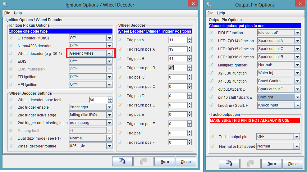
Ignition Options / Wheel Decoder and Output Pin Options - Ensure only the Wheel Decoder - Generic Wheel option is set. This example is for a 4cy wasted spark so it has ONLY Spark A and Spark B set! Please see the Basic Config manual for more.

If directly driving your coils from the MS ECU then set dwell as:

Please note that these will need to be tuned, see the Dwell section of this
manual.
Following Example
is when the Second Sensor is on the CAM with 1pulse per cam revolution:
(Primary sensor = Crank 60 teeth)
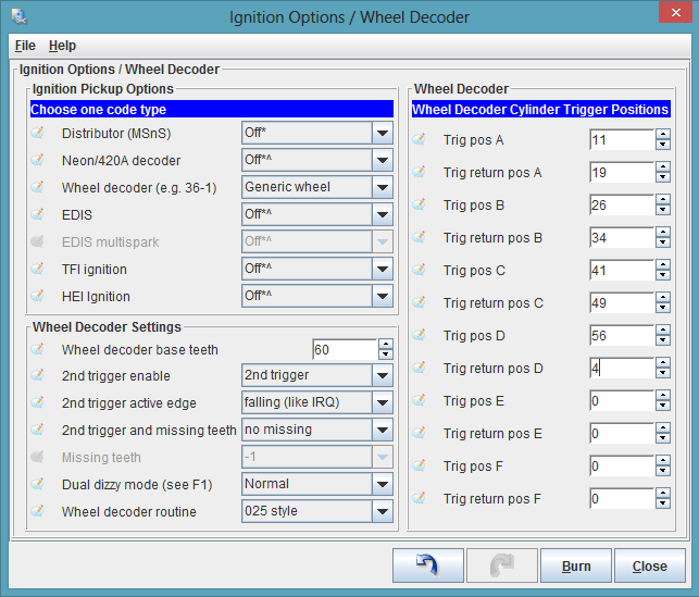
Ignition Options / Wheel Decoder and Output Pin Options - Ensure only the Wheel Decoder - Generic Wheel option is set. This example has Spark A, Spark B, Spark C and Spark D set! It could run a COP setup (4 cy) or a wasted spark 4cy. Please see the Basic Config manual for more.
| Primary teeth = 60 | Primary teeth = 4 |

If directly driving your coils from the MS ECU then set dwell as
:
Please note that these will need to be tuned, see the Dwell section of this
manual.
Finding Edis in North America -- Finding Edis in Europe -- Internal Mods to the MS ECU -- Edis Wiring Diagrams -- TunerStudio Settings
Fitting the VR Sensor and the 36-1 wheel
Ford's Electronic Distributorless Ignition System (EDIS) is an ignition system that does NOT require a cam position signal. It can function with just a variable reluctor crank position sensor (VR sensor) and a 36-1 tooth wheel (36-1 means '36 teeth minus one', and refers to 36 evenly spaced teeth, one of which has been removed).
Because it doesn't need a camshaft position sensor, EDIS is a particularly easy way to replace distributor ignitions when retrofitting older engines with a modern computer programmable ignition, but we now recommend directly driving the coil packs from the MS ECU using the VB921 FET's. This does away with the EDIS module, so all thats needed is the 36-1 wheel, a VR sensor and the coil packs. Please see the VR input Sensor wiring and the Direct Coil Drive Wiring section.

If you alread have an EDIS setup and want to use it then these are the mods for it:
The EDIS system is made up of:
EDIS module,
crank wheel,
crank variable reluctor sensor (VRS), and
one or more coil pack(s).
Finding Edis 4 in North America:
Early to mid 1990s Ford Escort/ Mercury Tracer with base 1.9L SOHC engine were fitted with the EDIS4 system. You can tell the engine because it has a tubular aluminium (NOT cast) inlet manifold.
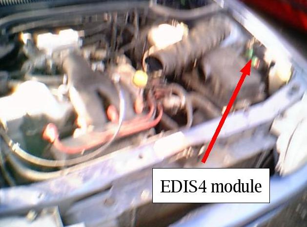
The EDIS4 module is mounted just behind the fuse box on the drivers side of the engine bay, it has a label on the plug that says EDIS4. The bolts are 10mm AF. You are advised to remove the fuse box first for easier access. Cut off as much as the harness as you can.
Looking toward the passenger side end of the engine, the VR sensor is above and to the left of the end of the crankshaft. The easiest way to access the sensor is to remove the front wheel (if it's not already removed), lie on your back, and reach up from the bottom to access the sensor mounting bolts. The bolts are either small metric or star bit. Once it's off, the cable is most easily cut from the top.
The crank pulley bolt is 19mm. You will need to stop engine
from turning, various methods have been suggested. 1) remove the head, put
some rocks into the bore and refit the head. 2) remove a spark plug and
put a long bar down the hole 3) remove a plug from cylinder with piston
at BTDC and coil in some rope, remove rope when finished.

 Click on images for a larger picture
1a) EDIS4 module
1989-1993 Fiesta XR2i 1.6
1990-1992 Fiesta RS turbo
1989-1994 Escort 1.6i
1990-1994 Orion 1.6i
Modules are all in the engine bay and typically located in the middle of
the bulkhead or the right hand side as you face the car.
Known part numbers are: 89FB-12K072-AC, 91AB-12K072-AA
 Orion CVH MPI
 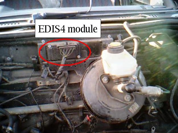 Fiesta / crossflow Escort
 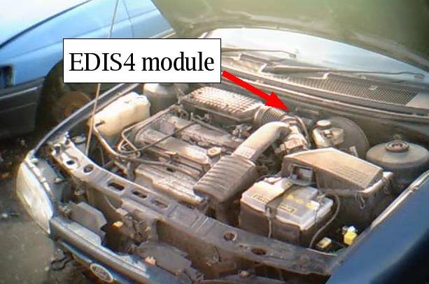 Mondeo with 1800/2000 engine.
Location of the VR sensor varies. On the small CVH engines
it pokes through the rear flange of the engine towards the flywheel. 1.8CVH
Sierra has one on the front. 2.0DOHC Sierra/ Granada is in the block at
the left side way below the inlet manifold. Duratec V6 (Mondeo) is mounted
near the front, it also has a cam sensor that works too.
The mounting bolts are either small metric or star bit.
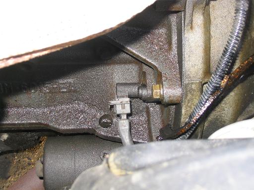 Escort / Fiesta location on engine flange above starter.
Do not confuse with the ESC II hybrid module which has a vacuum
tube and comes on the carb model cars.
There is also an aluminium one to avoid as well.
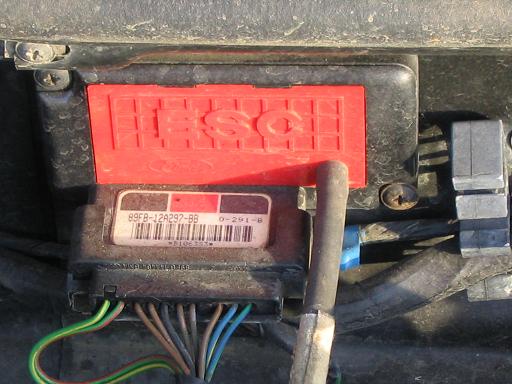 Click to enlarge picture of plastic hybrid module to avoid.
1b) EDIS6 module
up to 1995ish Mondeo V6 automatic
Ford/Cosworth Granada Scorpio 24v V6
Module located rear left of engine bay as you face the car.
Known part numbers are: 90GB-12K072-AB
1c) EDIS8 module
Chances of finding one of these in a scrapyard are very low! Not known to
have been installed on any European built vehicles. Your best bet is either
to import a module from the USA or buy new. I would suggest buying the other
bits locally.
For connectors try one off another car if all the wires are in use or one
off an ESC module. The number of wires used in the connector varies so check
they are all there!
There is a possibility of using 2 EDIS4 modules to drive a V8. But now that
the MS ECU can directly drive 4 coils (V8 in wasted spark) this is no longer
necassary.
2) 36-1 trigger disc
The 1.8CVH Sierra has a useful disc pressed onto the back of the crank pulley
All of the other CVH installs have the trigger teeth cut into the flywheel
and so are useless.
For a scrap yard trigger disc, remove from 1.8CVH Sierra.
You will need to stop engine from turning, various methods have been suggested.
1) remove the head, put some old bolts or other junk into the bore and refit
the head.
2) remove a spark plug and put a long bar down the hole
3) remove a plug from cylinder with piston at BTDC and coil in some rope,
remove rope when finished
4) Jam something into the flywheel teeth
 Sierra pulley/trigger assy and VR sensor
If you are after a pressed steel disc, try part no. 1078767,
about £12 from Ford, this came on the 16v DOHC Granada engines, alternatively
wheels are available to order from HERE
3) VR sensor
Usually it is easiest to get from the same vehicle as the EDIS module so
the loom wiring colours match.
Or any vehicle with a trigger disc will yield one, so CVH Fiesta/Escort/Orion
or Fiesta with Valentia (crossflow) engine with ESCII hybrid, DOHC Sierra/Granada,
Mondeo. See HERE for more on VR sensors.
4) Coil pack/s
Usually it is easiest to get from the same vehicle as the EDIS module so
the loom wiring colours match.
Also CVH Fiesta/Escort/Orion/Sierra or Fiesta with Valentia (crossflow)
engine with ESCII hybrid, Zetec e.g. Mondeo.
These 4cyl engines have 4 post coils. The V6 Mondeo has a 6 post coil. 8cyl
applications use two 4 post coils.
Carb Fiesta Valentia engines have the coil pack on the rear of the block.
Mondeo Zetec have the coil pack beside the rocker cover. The HT leads are
usually very short, but the ends can be removed with some lubricant and
re-used on new leads by re-crimping them with a pair of pliers. It can be
handy to get 2 sets so you can practice a little first.
Input Mods for V3.0 PCB:
Output mods for V3.0 PCB:

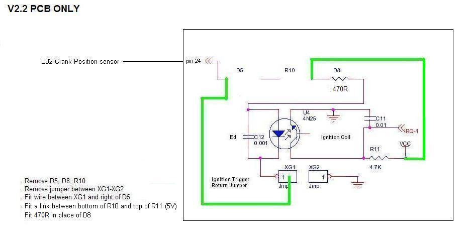
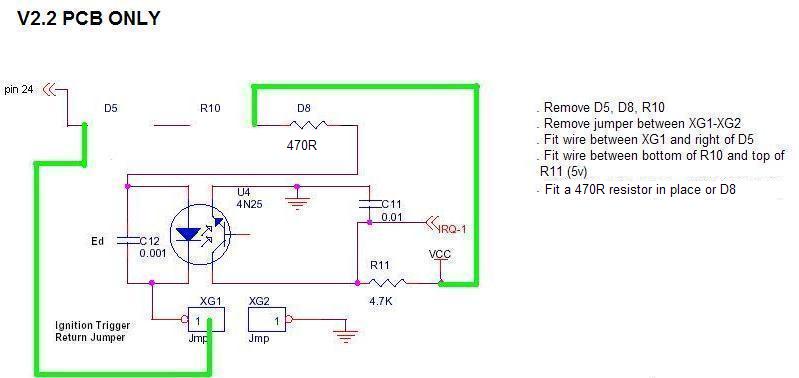
V2.2 PCB ONLY


Edis Wiring for a V3.0PCB:
Edis Wiring for a V2.2 PCB:
Ensure that the ONLY ignition option in Ignition Options / Wheel Decoder and Output Pin Options is EDIS and that LED17 is set as SparkA, NO other outputs must be set as a Spark Output.


Fitting the VR Sensor and the 36-1 wheel
Assuming you have obtained a suitable 36-1 wheel, you need
to establish the correct relationship between the VR sensor and disc.
There are two methods to visualise the relationship with the same outcome.
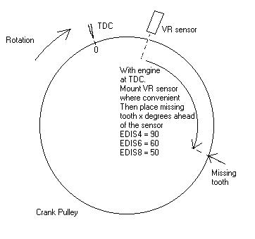
SPECIFIC-ANGLE is defined as follows: EDIS4=90, EDIS6=60, EDIS8=50
EITHER
1) Turn your engine to SPECIFIC-ANGLE degrees before TDC (check direction
of rotation!). Mount the VR sensor wherever is convenient and mount trigger
disc so that the centre of the sensor aligns with the centre of the missing
tooth.
OR
2) Set your engine at TDC, then put the missing tooth either 9, 6 or 5 (depending
on no. cylinders) teeth in front of the sensor. (Count from missing tooth
in opposite direction of rotation) This will put the centre of a tooth
central to the sensor.
i.e. EDIS4 = 9 teeth, EDIS6 = 6 teeth, EDIS8 = 5 teeth (Ensure you know the direction of rotation for your engine)
Direction of rotation for this example is Anti-Clockwise
for below

Direction of rotation for this example is Clockwise for below
There should be 0.75 - 1.0mm gap between sensor and wheel.
To test this alignment it is best to run the EDIS in limp home mode. This can be achieved by disconnecting the SAW plug/socket or switching off/unplugging the ECU. Fit your strobe onto no.1 plug lead as normal (you may need to try the other tower of the pair). Ensure EDIS still has power and crank your engine, check that the timing is exactly 10deg. If not, adjust your sensor until it is. It is safe to idle the engine with the SAW lead disconnected, timing should be rock solid at 10BTDC. Don't forget to reconnect the plug when done!
Optional: multi-spark mode
NOTE: Multi-spark is currently under test with MSnS-extra firmware.
1) First get your engine running with multispark off, then:
2) Go to the Advanced >Advanced code options and set EDIS multispark
on. Turn megasquirt off then on.
2) Check your timing with a strobe at low rpm (less than 1100.)
3) If the timing is locked to 10BTDC then the module is not compatible.
4) If the timing varies as expected (you can use Fixed on Spark>Spark
Settings to set e.g. 5 or 15) then it is compatible.
5) If in doubt leave it switched off.
6) Advanced tester can experiment with the max rpm. The patent states 1100rpm.
Ford Thick Film Integrated IV Ignition Systems (TFI)
MS Input Wiring -- MS Output Wiring -- TFI Schematic -- TunerStudio Settings
The code is only designed for "push start" modules which are claimed to be grey in colour. Computer controlled dwell modules are black. Maybe this is USA only data because the Push Start module I used is mainly black. On a push start the START wire will run to the ignition switch. On a CCD that pin is IDM and will run to the ECU.
ALPHA testers desired for CCD modules. Try as below but set to dwell control instead of 50% duty.
Here is the pinout of a typical dizzy mounted module, consult you Haynes manual if necessary.

My suggestion to users is to get your car running fuel only before throwing timing into the mix. The TFI dizzy has a limp home 10deg mode so if the SPOUT wire is left unplugged it will continue to spark just fine. This way you will prove that you can idle with Megasquirt before adding timing control.
Board Mods - input side
The input side on the MS board is fairly straightforward, most boards will
need no changes.
For all boards you connect the TFI PIP wire to the Megasquirt TACH input
which is DB37 pin 24.
Input Mods: See also the TFI Output mods drawings HERE
V3.0 PCB ONLY:
V2.2 PCB ONLY:
NOTE!! If you are using an aftermarket spark box like
MSD you can skip the special circuit and use a regular "LED17"
spark output. See the MSD Output Wiring under HERE.
If you do this you must also configure your spark type as MSnS and NOT
TFI in Codebase and Output Functions!!!
When the code is set to TFI it expects you to use the TFI module to fire
the coil and provide cranking spark.
When using the TFI module to drive the coil carry out the following: (NOT for an MSD)
V3.0 PCB ONLY:

V2.2 PCB ONLY:

Set the Codebase and Outputs page as follows:

Set the Trigger Angle to 10 degrees and spark output
inverted to Yes.
Set the Dwell to:
For more technical details of the Ford TFI system please see this document HERE.
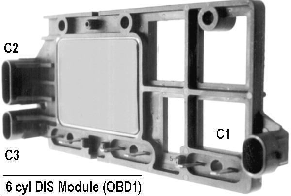
There were a number of different kinds of General Motors HEI modules:
* 4 pin module - electronic ignition, but doesn't
do computer timing control, top left
* 7 pin module (large) - electronic module that does timing control,
used with coil-in-cap distributors, top right
* 7 pin module (small) - electronic module that does timing control,
used with some external coil distributors, bottom right
* 8 pin module - electronic module that does timing control, used
with most V8 external coil distributors, bottom left
* 5 pin module - rare and not discussed here. not shown

Internal Mods for V3.0 PCB's
HEI7/8 mode will use the Opto/Hall input, so the VR components
are not required.

Internal Mods for V2.2 PCB's

Wiring the HEI module:

In Ignition Options / Wheel Decoder and Output Pin Options set the HEI Ignition option, set LED17 as SparkA out and LED19 as Spark B output.

In Spark Settings ensure "Trigger Angle" is set to 10 deg and Inverted Spark Output = NO.
Set the dwell to:

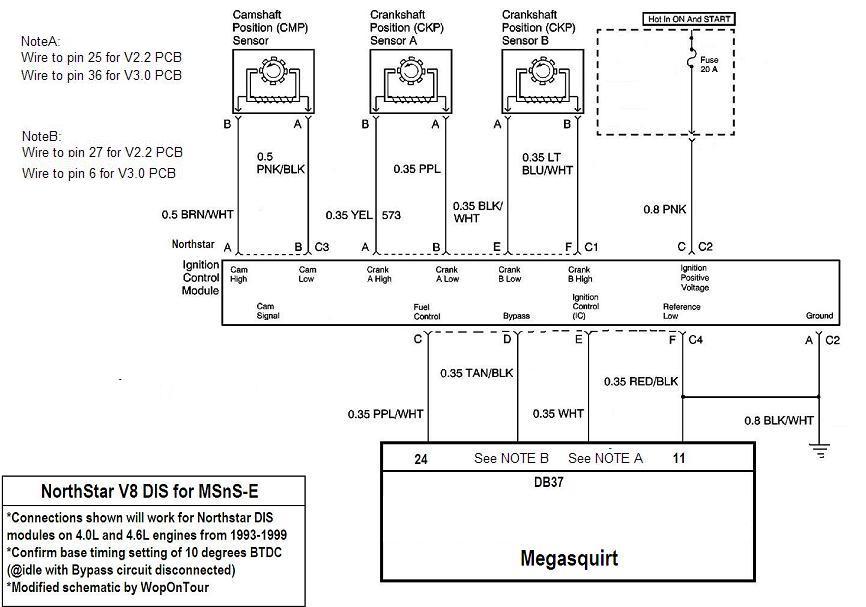
GM DIS Wiring -- Saturn 1.9L DIS Wiring -- North Star Wiring
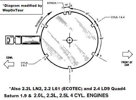
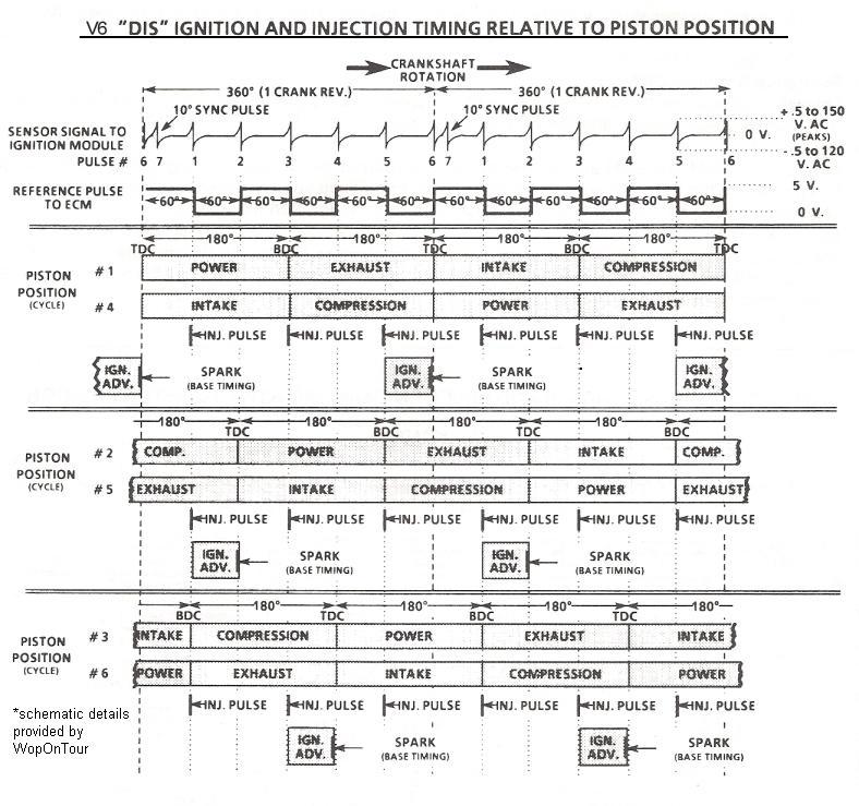
Most of the following explanation comes from "WopOnTour" - many thanks!! Please read his full description HERE
4cyl and 6cyl engines are essentially identical schematic. The only difference is the 3X shown (toggles voltage every 60 degrees) becomes a 2X (60/120) as the and the 4cyl DIS coil will toggle the reference voltage on every 3rd 60 degree increment (180 degrees)
NOTE: This will NOT work for 2005 3.5L HV-V6 using the new "quick start" DIS (or any other up-integrated DIS that does not use a "Bypass" circuit) I also have concerns on the 87-88 VIN-D Quad 4 engine that (for whatever reason) has the 7X reluctor notches machined at TDC. So you may need to eliminate Bypass altogether and run "cranking EST"
ALSO NOTE: Depending on the DIS module used you MAY have to bypass the Opto coupler within the MS directly connecting the IGN REF input at pin 24 to the opto output.
V3.0 PCB mods:
V2.2 PCB mods:

 Thumb nails, click to enlarge.
*Note: The injection events shown every 120 degrees is just for startup on the stock GM ECM, after 400 rpm is achieved the simultaneous injection event occurs once per crankshaft revolution (or twice per cycle in MS terms)
 Thumb
nails, click to enlarge.
Thumb
nails, click to enlarge.
You MAY want to make sure there is identical ground potential
between the MS and the DIS module by connecting Pin F of the DIS module
to the same engine ground point as your Megasquirt.
Wire the Megasquirt as the GM DIS wiring above, then wire the external as:

In Spark Settings ensure "Trigger Angle" is set to 45deg and the Trigger Angle Addition to +45 and Inverted Spark Output = YES or the advance will be about 120 degrees from desired. Then in Codebase and Output functions ensure LED17 is SparkA and LED19 is SparkB, set the Dwell to Fixed Duty - 50% Duty.
Noted that advanced displayed in TunerStudio DID NOT include approx 10 degrees of advance
Wire the Megasquirt as the GM DIS wiring above, then wire the external as:

In Spark Settings ensure "Trigger Angle" is set to 45deg and the Trigger Angle Addition to +45 and Inverted Spark Output = YES or the advance will be about 120 degrees from desired. Then in Codebase and Output functions ensure LED17 is SparkA and LED19 is SparkB, set the Dwell to Fixed Duty - 50% Duty.
Noted that advanced displayed in TunerStudio DID NOT include
approx 10 degrees of advance
The 2 connector pinouts are as follows:
Connector 1 (C1)
PN#12084220 / 6-way but only 5 used
A- IGN+ (fused)
B- Not Connected
C- EST (timing signal from MS)
D- IGN REF (to MS TACH input)
E- Tach (Optional)
F- Bypass (5V applied by MS after engine start)
* I recommend you always put an inline connector in the Bypass circuit so
that you can easily drive the DIS to base timing fail-safe mode (Bypass)
Connector 2 (C2)
PN#12084415 / 5-way
A- CKP+
B- CKP-
C- CKP Shield (RF Gnd)
D- REF LO
E- GND
Note: It's not mandatory to use Saturn Parts here. You can optionally use the DIS module and connectors from another "MSnS-E Compatible 4 cyl Engine".
Should work for any Northstar WITHOUT coil on plug or on newer engines (not the VVT LH2) with the addition of an older DIS module and coil pack. THIS HAS NOT BEEN TESTED ON A RUNNING ENGINE YET SO THE TRIGGER ANGLES NECCESSARY TO GET 100% TIMING ACCURACY HAS YET TO BE CONFIRMED Below is the DIS waveform index for the Northstar and the DIS to MS wiring schematic

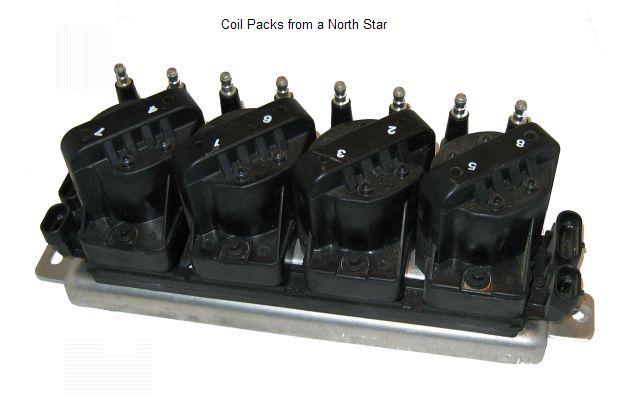 Click to enlarge
Buick Computer Controlled Coil Ignition (C3I)
Most of the following explanation comes from "WopOnTour"
- many thanks!!
I have been doing some extensive testing on the Buick 3800 Computer Controlled
Coil Ignition (C3I) system for MSnS-E (Fidle as spark control) using my
MS and a 2000 C3I mockup that I have. The scope waveforms and patterns look
very promising.Here's what I have learned so far (although keep in mind
this was done in a mock-up state only and NOT on a running engine)
NOTE: Depending on the C3I module used you MAY have to bypass the Opto coupler within the MS directly connecting the IGN REF input at pin 24 to the opto output. The best option is to post a thread on the MSEXTRA forum giving details of your setup before you start.
In order to potentially run the C3I ignition as used by the 3800 with MSnS-E you will need to REROUTE the following signals from the C3I module to the MS:
- connect the purple/white wire (C3I ignition module terminal D) to PIN24 of the DB37@Megasquirt. This C3I signal is commonly labeled "low resolution engine speed signal" is actually a digital 3X (ie transitioning every 120 degrees of crankshaft and) near identical to the old DIST REF but is synthesized by the C3I module from the 18X hall-effect input (18/6=3) *NOTE-This circuit was previously routed to the oe ECM.
- connect the "IC Timing signal" (aka 5V Bypass) which is the Tan/Black wire at terminal B of the C3I ignition module to pin 27@DB37 of Megasquirt. *NOTE-This circuit was previously routed to the oe ECM.
- Finally the Electronic Spark Timing (IC timing control) a white wire at pin A of the C3I ignition module to the reconfigured LED17 @ Pin25 at the Megasquirt DB37 connector. *NOTE-This circuit was previously routed to the oe ECM.
V3.0 PCB mods:
V2.2 PCB mods:
External Wiring for all MS PCB's:


Please Note: You MAY want to make sure there is identical ground potential between the MS and the C3I module by connecting Pin L of the C3I module to the same engine ground point as your Megasquirt.
MOST of the remaining connections at the C3I ignition module MUST REMAIN connected as factory. These include IGN+ (terminal P), Ground (terminal K) and the circuits to the various hall-effect sensors (terminals G,H,J,M and N) While all of these sensors are not necessary they do share a certain amount of circuitry (see schematic) and will facilitate future possible use of these signals (for possible enhancement through wheel decoding or maybe SFI on the MSII)
The following circuits at the C3I ignition module that can
be safely removed as they went to the OE ECM. (actually it's recommended
that these circuits just be either "clipped" at the ignition module
to maintain connector seal integrity or just insure they are properluy "dead-ended")
So you can safely "clip the wires to IGN MODULE terminals
C (Medium Resolution Engine Speed Signal)
F (Camshaft Position Signal) and
L (low reference)
*The wire at E can also be clipped as AFAIK was never used anywhere.
This should work for any Buick 3800 from 1988 to present
In Spark Settings ensure "Trigger Angle" is set to 70deg.
Codebase and Output functions ensure LED17 is SparkA and LED19 is SparkB, set the Dwell to Fixed Duty - 50% Duty
5 Cylinder Engines (Audi, etc)
For distributor based engines then this is a straight forward MSnS setup see HERE, but for COP setups you will need 2 trigger inputs. Whilst it is possible to do it with a cam sensor, it is easiest to do it with 2 sensors, one on the crank and the other driven off the cam. The first sensor off the crank needs to be at least 5 teeth equally spaced, a 60-2 wheel would be best and shouldn't be too hard as most Audi's use these anyhow. The second sensor needs to pick up 1 pulse per cam revolution. This would need a second sensor input circuit wired to Pin11 of U1, the circuit would depend on the type of sensor used, but all circuits will need the opto-isolator between the sensor and Pin11 of U1. See HERE
Twin Cam 4G63 and 4G9
powered DSM (Eclipse / Talon / Lazer)
Double Over Head Cam engines (DOHC)
V2.2 wiring mods -- V3.0 wiring mods -- External wiring diagram -- TunerStudio Settings
These instructions are based on information from Jerry at
DIYAutoTune.com and from Zainal
Hasnan, many thanks to both of them.
This is for 1st gen DSM with the 4G63 engine as well as the 4G9 series engine:
4G91 DOHC = 1.5 liter
4G92 DOHC = 1.6 liter
4G93 DOHC = 1.8 liter

There are two 'sets' or 'rings' of holes in the optical CAS. The outer ring
of holes is read by an optical sensor and then sent to the ECU, this is
referred to as the CKP signal. Likewise the inner ring with only
one hole is also read by an optical sensor, sent to the ECU and is referred
to as the CMP signal.
Outer Ring - Crank Angle Sensor (RPM) - CKP
Inner Ring - Top Dead Center Sensor - CMP
The theory here is to drive the CKP as the main trigger input (pin24 of the db37) and the CMP as the second trigger input (pin11 of U1).
You should be able to swap the 1G DSM 4G63 CAS assembly into
the 2G DSM 4G63 and use these instructions as well. If not see the SOHC
instructions HERE
For the CMP trigger input (Inner ring):

For the CKP trigger input (Outer ring):

V2.2 output wiring mods:
(the following mods will trigger the stock ignitors. It is felt that
it is easier to get running using the original ignitors so this is the recommended
and tested method. But if you want to drive the coils directly rather than
through the ignitors then please see the Direct Drive
section, the Spark Inverted will then = YES!)
For the CMP trigger input:

For the CKP sensor input:

V3.0 PCB Output wiring MODS:
(the following mods will trigger the stock ignitors. It is felt that
it is easier to get running using the original ignitors so this is the recommended
and tested method. But if you want to drive the coils directly rather than
through the ignitors then please see the Direct Drive
section, the Spark Inverted will then = YES!)
External wiring diagram for 4G63 all board versions:

Settings for 4G63 all board versions:


(Please note: The Trigger Angle setting will need adjusting more accurately
using a strobe and a Fixed Angle see HERE)
(It is felt that it is easier to get running using the original ignitors
so this is the recommended and tested method. But if you want to drive the
coils directly rather than through the ignitors then please see the Direct
Drive section, the Spark Inverted will then = YES!)

Mitsubishi and Proton distributor based engines, Single Over Head Cam (SOHC)
V2.2 wiring mods -- V3.0 wiring mods -- External wiring diagram -- TunerStudio Settings
Thanks to Zainal Hasnan for the following information and
pictures.
The SOHC usually runs a distributor. These engine types are:
Mitsubishi and Proton NA (They share the same engines)
4G13 1.3 liter sohc injection.
4G15 1.5 liter sohc injection
4G92 1.6 liter sohc injection
4G63 2.0 liter sohc injection
There are 2 types of distributor that runs these engines:
| Vanes type sensor. |
Windows type sensor
|


However, they only have 1 inner windows or vane for the tdc sensor.
To run these without modifying it to the same spec as the 4G63 then it is best to use MSnS mode using the outer (4 vaned) sensor and keep the distributor.
V2.2 output wiring mods:
(the following mods will trigger the stock ignitors. It is felt that
it is easier to get running using the original ignitors so this is the recommended
and tested method. But if you want to drive the coils directly rather than
through the ignitors then please see the Direct Drive
section, the Spark Inverted will then = YES!)

V3.0 PCB Output wiring MODS:
(the following mods will trigger the stock ignitors. It is felt that
it is easier to get running using the original ignitors so this is the recommended
and tested method. But if you want to drive the coils directly rather than
through the ignitors then please see the Direct Drive
section, the Spark Inverted will then = YES!)
External wiring diagram for SOHC distributor based 4G63 all board versions:

TunerStudio Settings for SOHC distributor based 4G63 engines

(Please note: The Trigger Angle setting will need adjusting
more accurately using a strobe and a Fixed Angle see HERE)
(It is felt that it is easier to get running using the original ignitors
so this is the recommended and tested method. But if you want to drive the
coils directly rather than through the ignitors then please see the Direct
Drive section, the Spark Inverted will then = YES!)
Mods for a 2 Rotor Mazda engine -- Mods for a 3 Rotor Mazda engine
The rotary engine is obviously fundementally different
to a normal 4 stroke engine, but it can still be controlled by the MS ECU
running the MS1 Extra code as long as a few rules are followed. With a four
stroke engine, in 720° of crank rotation it will draw in the equivalent
amount of air as its rated displacement. But with a rotary engine in the
same 720° it draws in twice its rated displacement.
Therefore:
If you have a 2 rotor (Mazda 13B) engine (1.3 L) it's really like a 2.6L
4 cyl 4 stroke engine.
If you have a 3 rotor (Mazda 20B) engine (2.0L) , it's really like a 4L
6 cyl 4 stroke engine.
The rotary engine has a leading and a trailing ignition (2 plugs per rotor) the leading fires first then the trailing fires a few degrees later. On a 2 rotor engine the leading can be fired in a wasted spark format, but on a 3 rotor engine the leading must be driven by 3 individual coils e.g. COP. Simply set the system up as a 6 cylinder engine running wasted spark, this will fire the 3 spark outputs (Spark A, B and C) every 360 deg of crank rotation. Please see the Rotary Trailing Setup HERE for more info before running your engine. For more setting details on the rotary engines please see HERE.
2 Rotor Mazda Engine (13b 1.3L) wiring diagrams:
In order to use the BAC valve please see the hardware mods for the Idle valve HERE.
V2.2 PCB internal mods:
Input mods:
The MS V2.2 ECU will need to have 2 VR conditioners (LM1815), the following circuit contains two (LM1815):
This circuit's connections assume that the pcb will be mounted internally (inside the MS ECU's case) This can be mounted externally but the connections for Ne+ and G+ would connect directly to the conditioner rather than via the db37 connector.

|
DigiKey part
numbers:
|
Farnell
part numbers
|
|
1K resistor = 1.0KQBK-ND |
1K resistor = 509-164 |
Please note: Above part numbers will need checking, some components will come with a minimum order in multiples of 5 and 10.
If fitting the above circuit external to the MS ECU then
the Ne+ wire (24 tooth VR sensor positive lead) and the G+ wire (2 tooth
VR sensor positive lead) on the CAS need to be wired directly to the above
circuit:
NoteA : Connect to Ne+ wire.
NoteB: Connect to G+ wire
The VR sensor's grounds should ALL be grounded back to the board with the
lm1815 on it.
The output of U1 (above) on pin 12 should be wired to pin 6 of U4 on the megasquirt board. U4 is a six pin chip on the MS ECU board, the opto-isolator, this uses the output transistor within the opto as an inverter. The output of U2 (above) should be wired through a 1k resistor to pin 11 on the CPU.
Output Mods for V2.2 PCB:

External wiring for V2.2 PCB:

V3.0 PCB internal mods:
As the V3.0 PCB already has a built in VR conditioner then there's only the need to build one extra conditioner for the 2 toothed CAS signal. The following diagrams assume the conditioner will be mounted inside the MS ECU case.

|
DigiKey part
numbers:
|
Farnell
part numbers
|
|
1K resistor = 1.0KQBK-ND |
1K resistor = 509-164 |
Please note: Above part numbers will need checking, some components will come with a minimum order in multiples of 5 and 10.
You need to connect the output of the LM1815 (Pin 12) straight to U1 pin 11 via a 1K resistor.
Wire the MS internally for a VR input, link TSEL to VROUTINV and link VRIN to TACHSELECT:


V3.0 PCB Output wiring:

External wiring for V3.0 PCB:

3 Rotor Mazda Engine (20B 2.0L) wiring diagrams:
I need some help here, anyone
done a 3 rotor they can give me the info for ?
If so please email me philip.ringwood(at)ntlworld.com
V3.0 Mods -- V2.2 Mods -- External Diagram -- TunerStudio Settings
Input Mods:
Output mods:

Input Mods:
Output Mods:

Toyota VAST External Drawings:


Trigger Input Wiring Diagrams:
Wiring for V3.0 PCB -- Wiring for a V2.2 PCB
How you should connect a Hall sensor to the MS ECU all depends on what comes out of the Hall sensor.
Turn the engine until cylinder 1 should fire. Turn the distributor until the rotor point to the contact for cylinder 1 in the distributor cap.
Make sure one of the metal finger edges are close to the Hall sensor, either going in or out will be fine.
Turn the engine backwards until the edge is well out of the Hall sensor. Measure the output voltage from the Hall sensor Turn the engine forward until the edge has passed through the Hall sensor. Measure the output voltage.

High to low. For Hall Sensors that are Hi (+5V to 12V) when there is no tooth infront of the sensor and Lo (Gnd) when the edge of the tooth is infront of the sensor:

Low to High. For Hall Sensors that are Low (Gnd) when there is no tooth infront of the sensor and Hi (+5 to +12V) when the edge of the tooth is infront of the sensor
(This appears to be the most commonly used sensor from what I understand, so if in doubt try this one first)

Hall or Optical input sensor wiring for V2.2 PCB
How you should connect a Hall sensor to the MS ECU all depends on what comes out of the Hall sensor.
Turn the engine until cylinder 1 should fire. Turn the distributor until the rotor point to the contact for cylinder 1 in the distributor cap.
Make sure one of the metal finger edges are close to the Hall sensor, either going in or out will be fine.
Turn the engine backwards until the edge is well out of the Hall sensor. Measure the output voltage from the Hall sensor Turn the engine forward until the edge has passed through the Hall sensor. Measure the output voltage.
Hi to Lo. For Hall Sensors that are Hi (+5V to 12V) when there is no tooth infront of the sensor and Lo (Gnd) when the edge of the tooth is infront of the sensor :

Lo to Hi. For Hall Sensors that are low
(Gnd) when there is no tooth infront of the sensor and Hi (+5 to +12V) when
the edge of the tooth is infront of the sensor
When hall sensor output is 5V use:

Lo to Hi. For Hall Sensors that are low (Gnd) when there is
no tooth infront of the sensor and Hi (+5 to +12V) when the edge of the
tooth is infront of the sensor
When hall sensor output is 12V use:

V3.0 PCB Wiring -- V2.2 PCB Wiring
Example of a Ford Variable Reluctance Sensor (VR Sensor), these are positioned so they detect the teeth on a crank wheel. When the edge of a tooth (piece of ferrous metal) passes them at high speed and at a very close proximity (Gap of 0.75 - 1.0mm) they generate a small signal.


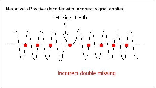
The following diagram shows what happens when the VR jumpers
on the V3.0 PCB or the VR sensor is wired incorrectly:
(VR sensor ground signal wired to pin24, the sensors signal +ve wired to
the screen and the VROUTINV linked to TSEL)
or
(VR sensors +ve signal wired to pin24 , the sensors ground wired to the
screen and the VROUT linked to TSEL).
The trigger points (where the signal goes through the line on the positive
going slope) are shown in red. The time between the trigger points is consistant
untill the missing tooth comes passed the sensor. The gap has increased
a little (not fully) as the wave returns to the line but as it has to wait
untill the next positively going slope the next gap is also decoded as another
missing tooth.
This diagram shows the jumpers and the VR sensor wired correctly;
(VR sensor +ve signal wired to pin24, the sensors ground wired to the screen
and the VROUTINV linked to TSEL)
or
(VR sensor ground signal wired to pin24 , the sensors +ve wired to ground
and the VROUT linked to TSEL).
This time the negative side of the slope is used as the trigger edge. This
means that as the missing tooth passes the sensor it doesnt trigger the
ECU untill the fall from the next tooth (Tooth 1).

VR Sensor Wiring for a V3.0 PCB
Adjust both the pots fully counter-clockwise (ccw) as a starting point, they don't physically stop turning, you will hear them click when they are fully one way. Generally the pots end up either fully ccw or a few turns clockwise from there.
VR input Sensor wiring for a V2.2 PCB
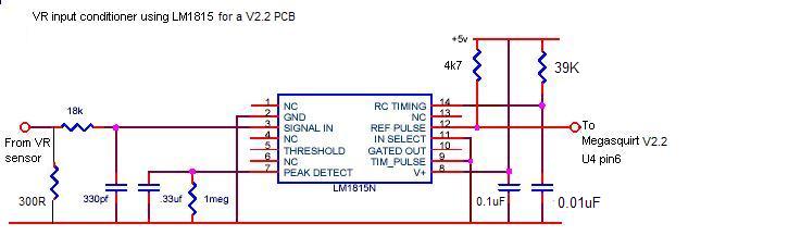 V2.2
PCB ONLY
V2.2
PCB ONLY
|
DigiKey part
numbers:
|
Farnell
part numbers
|
|
300R resistor = 330QBK-ND |
300R resistor = 543-251 |
Please note: Above part numbers will need checking, some components will come with a minimum order in multiples of 5 and 10.
Second VR Sensor Input for a V2.2 and V3.0 PCB's
This is the same circuit for a V2.2 and a V3.0 PCB when adding a second Variable Reluctor (VR) sensor. Another option is to build the VR conditioner from the V3.0 PCB. If you are using a second Hall sensor input then see HERE

|
DigiKey part
numbers:
|
Farnell
part numbers
|
|
1K resistor = 1.0KQBK-ND |
1K resistor = 509-164 |
Please note: Above part numbers will need checking, some components will come with a minimum order in multiples of 5 and 10.
Second Trigger Input for V2.2 and V3.0 PCB's
Many Mazda and Toyota engines utilise Nippondenso ignition
which uses a dual wheel crank angle sensor (CAS) which has one 24 tooth
wheel and a 2 or single tooth second wheel. This is also needed to run a
5cylinder engine in COP mode it can also be used inventively to give 4 cyl
COP or could be used with the dual pickup crank trigger from SDS for 4cyl
wasted spark. For setting up TunerStudio see HERE
.
If using a VR sensor then see the Second VR Sensor Input section for your
pcb version.
Depending on what sensor you have depends on the input stage, but all sensors will need an opto isolator setup like this unless your using the VR conditioner circuit.

|
DigiKey part
numbers:
|
Farnell
part numbers
|
|
1K resistor = 1.0KQBK-ND |
1K resistor = 509-164 |
Please note: Above part numbers will need checking, some components will come with a minimum order in multiples of 5 and 10.
Eliminating Cross Talk and Wiring Considerations for VR Sensors
Each of these VR conditioners is a very high input impedance amplifier. The VR voltages may be reasonably high and the insulation thin or there may even be a common wire for more than one sensor. Where this occurs, cross talk may result in the signals due to capacitive or inductive coupling, Fortunately, the resistance and hence impedance of the VR coils may be quite low and they can produce reasonable signals into low impedance loads. Ensure you use a screened cable for te VR sensor's signal from the sensor all the way to the MS ECU,(2 core audio phono cable is sufficient) ground the screened core only at the end of the ECU (e.g. pin 7 or 8 of the DB37), leave the sensor end of the screen insulated.
The signal below is a the output of 2 VR conditioners, one from each of the generic wheel (blue) and the second input (red). The cross talk is very noticeable and caused misfiring.

Tweaking the input resistor values as per the earlier version
of the V3 VR conditioners in the circuits above, results in a much cleaner
signal as shown below.

Using the pots can assist in setting the values of the load resistor, along with a bench testing facility for the VR sensors and trigger wheel. An Oscilloscope (or an adapter for the sound card of your PC with suitable software (eg Creative Wave Studio)) can greatly assist in fine tuning the input load resistors. Getting a good clean signal into MS is essential or you will spend hours trying to track down problems later on.
Luminition Optical Input for a V3.0 PCB
NB. If using luminition (MSnS Mode) you will have to rephase
your dizzy so that the trigger happens at say 60BTDC but the rotor is pointing
to a tower at 20BTDC.

Luminition Optical Input for a V2.2 PCB
NB. If using luminition (MSnS mode) you will have to rephase
your dizzy so that the trigger happens at say 60BTDC but the rotor is pointing
to a tower at 20BTDC.

Distributor points input for a V3.0 PCB
NB. If using points (MSnS mode) you will have to rephase your
dizzy so that the trigger happens at say 60BTDC but the rotor is pointing
to a tower at 20BTDC.

Distributor points input for a V2.2 PCB
NB. If using points (MSnS mode) you will have to rephase your
dizzy so that the trigger happens at say 60BTDC but the rotor is pointing
to a tower at 20BTDC.

Spark Output Wiring Diagrams.
MSD output wiring diagram for a V3.0 PCB
Set Spark Inverted = YES in Spark Settings and Dwell Duty to Fix - 50% and LED17(D14) to SparkA output in Codebase and Output Functions.
 V3.0
PCB
V3.0
PCB

MSD output wiring diagram for a V2.2 PCB
Set Spark Inverted = YES in Spark Settings and Dwell Duty to Fix - 50% and LED17(D14) to SparkA output in Codebase and Output Functions.
 V2.2
PCB ONLY
V2.2
PCB ONLY
V3.0 PCB Wiring -- V2.2 PCB Wiring -- External Wiring all versions -- TunerStudio Settings
Please note this is no longer the prefered method, the
Direct drive method is prefered. See HERE for
V2.2 or HERE for V3.0
The Bosch module 0 227 100 137 / 0 227 100 139 is designed to be used with
Hall effect and also takes care of the coil dwell period. The module trigger
when pin 6 is grounded, but the dwell control prevents it sparking on the
first trigger.

Pin 1 > (-) side of coil (is labelled "1" on
the coil)
Pin 2 > Good Ground
Pin 3 > not used
Pin 4 > Switched 12v* (eg from (+)side of coil, labelled "15"
on the coil)
Pin 5 > not used
Pin 6 > Spark output from Megasquirt (Pin 36 for a V3.0 PCB or pin 25
(X11) for a V2.2 PCB)
Pin 7 > not used. Not always present.
*source needs to supply a constant 12v when the ignition is
switched to "on"
If you use this module make sure you get the coil too. Normally there
should be a label on the coil saying it is for use in transistorized ignitions.
If you are getting this part from the junkyard, be sure to check that you
have the correct wiring pigtail - later (like early 1990s) pigtails have
only 4 wires - you need the connector with 6 wires.
See HERE for a list of suitable modules, etc.
Bosch Ignition Module Wiring for a V3.0 PCB
Bosch Ignition Module Wiring for a V2.2 PCB
Bosch Ignition External Wiring for all versions

In TunerStudio set the Codebase and Output Functions as:
Single Coil Direct Drive Output for a V3.0 PCB
These instructions are only suitable for single and twin spark outputs, for more than 2 sparks see the mutiple output section

Very Important: Set Spark Out Inverted = YES and set the Dwell to around 6.0mS for cranking 3.5mS for Running and 0.1mS for the Minimum Time as a starting point! Also set LED17 as SparkA output in Output Pin Options!! Read the Software manual for more info!!
Single Coil Direct Drive Output for a V2.2 PCB
It is recommended that V2.2 users fit a 15 or 25 pin db connector onto the case of the MS ECU. The reason is that the spare connectors on the V2.2 are not really capable of driving the current required for a coil unless you double them up (e.g. X11 and X12 as the ground X13 and X14 as the source). This is only suitable for a single VB921, if running more than one then see HERE.

Very Important: Set Spark Out Inverted = YES and set the Dwell to around 6.0mS for cranking 3.5mS for Running and 0.1mS for the Minimum Time as a starting point! Also set LED17 as SparkA output in Codebase and Output Functions!! Read the Software manual for more info!!
Two Coils Direct Drive Output for a V3.0 PCB
When running 2 coils directly from the ECU it is highly recommended you fit an extra copper cable (a peice of wire snipped from the leg of a diode or the like is fine) from the Spare terminal you are going to use (e.g. SRP4) to its terminal directly on the 37pin connector, (e.g. SPR4 to Pin 6), this is because the copper trace for the SPR connectors are designed for small signals voltages and not coil driver currents. This means you'll have to lift the MAP sensor up (unbolt it first :o) ). Also ensure the main earth lead is thick enough to cope, I use a 4mm cable connected to pins 8 and 9 of the DB37 connector (this is probably an over kill, but 0.75mm wire isn't good enough).
Start by wiring in the first VB921 as the single instructions (HERE)
The second VB921 can then be wired like this: (Please Note: I have assumed that R37 and R38 are not installed on this diagram, these need to be removed and linked out with a peice of copper wire. Alternatively keep R37 and R38 in place and bolt the new VB921 onto the lid of the MS ECU)
As a side note I generally mount the TIP122 Idle control FET in position R37 and the second VB921 as shown in position R38:
Very Important: Set Spark Out Inverted = YES and set the Dwell to around 6.0mS for cranking 3.5mS for Running and 0.1mS for the Minimum Time as a starting point! Also set LED17 as SparkA output and LED19 as SparkB output in Output Pin Options!! Read the Software manual for more info!!
External wiring diagram for a V3.0 PCB (2 coil drivers):

Two or more Coils Direct Drive Output for a V2.2 PCB
It is recommended that V2.2 users fit a 15 or 25 pin db connector onto the case of the MS ECU as the spare output traces on the pcb (X11, etc) are not up to driving a coil as they are too thin and will proably break.
Using the following diagram would mean removing the LED's from the pcb, simply remove them and do nothing else to the holes they leave.


Remember you only need to fit the same
amount of VB921's as you require outputs. e.g. 2 x VB921's (Spark A + B)
for a wasted spark 4cy, 4 x VB921's (Spark A + B + C + D) for a wasted spark
8cy, etc.
The outputs will NOT
work correctly if you choose: e.g. Spark A and Spark C for a 4cy
They MUST be selected in sequence A, B, C, D, E, F e.g. Spark A and Spark
B for a 4cy

Very Important: Set Spark Out Inverted = YES and set the Dwell to around 6.0mS for cranking 3.5mS for Running and 0.1mS for the Minimum Time as a starting point! Also set ALL the Spark Outputs used as SPARK A .. B .. C ..etc , in Output Pin Options, etc, ensure that all the Spark Outputs are set correctly!! Read the Software manual for more info!!
|
4 cylinder Wasted setup
|
6 cylinder Wasted setup
|
8 cylinder Wasted setup
|


Multiple Coils Direct Drive Output for a V3.0 PCB
When running more than 2 spark coil outputs directly from the MS ECU it is recommended that you fit a new connector (e.g. DB15) to the case (as we recommend for all V2.2 spark outs). The reason is that the ground cable / copper trace is not designed to take the current of the additional coils and it may also cause interference on the MS's ground plain. So to be safe simply drill and file out a slot for a new DB15 connector where the LED holes are in the front panel. Then mount the VB921's onto the lid of the case or underneath the MS board on another alluminium heat bus bar bolted through both sides. If mounting them on the lid, fit them so when the lid is in place the FET's end up on the bottom left corner, so when the lid is inverted like the picture they are at the top, this will ensure there is plenty of clearance for them inside the ECU when the lid is in place.
Note: This db15 is NOT the same as the V3.57 PCB db15, that can be used but you would need to strengthen the copper traces on the PCB and you would need to select different pins to the ones shown is these instructions!!!!
Using the following diagram would mean removing the LED's from the pcb, simply remove them and do nothing else to the holes they leave.
 3 x VB921's mounted on the lid.
  DB15 connector on front panel

Remember you only need to fit the same amount of VB921's as you require outputs. e.g. 2 x VB921's (Spark A + B) for a wasted spark 4cy, 4 x VB921's (Spark A + B + C + D) for a wasted spark 8cy, etc.
The outputs will NOT
work correctly if you choose: e.g. Spark A and Spark C for a 4cy
They MUST be selected in sequence A, B, C, D, E, F e.g. Spark A and Spark
B for a 4cy

Very Important: Set Spark Out Inverted = YES and set the Dwell to around 6.0mS for cranking 3.5mS for Running and 0.1mS for the Minimum Time as a starting point! Also set ALL the Spark Outputs used as SPARK A .. B .. C ..etc, in Output Pin Options, etc, ensure that all the Spark Outputs are set correctly!! Read the Software manual for more info!!
|
4 cylinder Wasted setup
|
6 cylinder Wasted setup
|
8 cylinder Wasted setup
|
Wasted Spark: This is used on a lot of 4 stroke engines and is where a pair of cylinders are fired together, one cylinder is on the compression stroke and the other on the exhaust stroke. The 2 cylinders that are fired are the pair that move together and are therefore opposite each other in the firing order. This setup therefore has multiple coils, usually 2 for a 4cy, 4 for a 8cy, etc. It does NOT have a distributor, as the spark plugs in the cylinders are connected directly to the coils.
e.g.
Rover V8 firing order = 1, 8, 4, 3, 6, 5, 7, 2
This would be 2 rotations of the crank, so 720 degs.
To fire this engine in wasted spark we would fire 1+6 together (as these
are opposite in the firing order), then 90deg later we would fire 8+5(again
these are opposite in the firing order), then 90deg later 4+7 then finally
a further 90deg we would fire 3+2, this repeats every crank revolution.
Ford 4 cylinder firing order = 1, 3, 4, 2 This
would be 2 rotations of the crank, so 720 degs.
To fire this engine in wasted spark we would fire 1+4 together (as these
are opposite in the firing order), then 180deg later we would fire 3+2 (again
these are opposite in the firing order), this repeats every crank revolution.
The cylinder that is fired on it's exhaust stroke is know as the "wasted
spark" as it produces no power. The benefits are that the coil fires
less often than when using a single coil and has more time to charge ready
for its next spark. This is very helpful at high revs when the charge time
can be very small.
There appears to be 2 different types of COP that manufacturers use:
A) One is a directly driven coil and has 2 or 3 wires, these have no integral amplifier (ignitor) and need to treated like a standard ignition coil. VB921's would be needed to fire these devices, see HERE for more info on wiring the MS ECU for these. Please note you would need to figure out what the pins were, there will be a 12V ignition feed, may be a ground and the fire signal (Spark A, B, etc)
B) The other type has 4 or 5, sometimes more, pins.
These have a built in amplifier (Ignitor) so they can be fired with a smaller
transitor if necassary (Note: You may still be able to use a VB921, it may
just need a pull up resistor depending on how your cop is designed.)
Some of the COPs with built in ignitors need a 5V signal, some need a 12V
signal to fire them, others needs a switched ground to fire them. Without
some experimenting it's difficult to tell which way around it needs unless
you can measure a working setup with a scope or meter or if you can find
the information from people who have already got a set like you have running.
Here are a few different wiring diagrams to try if you can find out which
way yours are fire:
5V pull up to fire
Ground switching to fire
VAG P/N 06B 905 115 COPs:
Thanks to Woh, Evolotion, Slow_Hemi6 and a few others here is how to set up the 4pin VAG COPs Coil PN 06B 905 115 as used on VW 1.8t and may other VAG cars (2001+). Theres no reason why, with a little measuring, you couldnt have a good guess at what a different type needed if you know where the pins connect.
Start by checking if you have a 120 -500 ohm resistor in the
cop to gound. Using a multimeter set to resistance to a suitable range,
check between pin 2 and 3 (this is the Spark Signal Input and Ground).
If you have a reading of around 120-500 ohms you need to go the 5V
PULL UP route.
If the impedance is higher, say ~1k then the Ground
switching route should work.
Coil PN 06B 905 115 L and R have been tested with the 5V Pull up method. Use the 'R' revision since the earlier 'L' revision has reliability issues.
Earlier than 2001 coils, PN - 06B 905 115, 06B 905 115 B and E have not been tested with these connections but have been reported to work using the Ground switching route.
The coil pack connections:
Pin 1: Connects to Pin 1 on all other coils and then to +12v ignition feed
(or fuel pump relay).
Pin 2: Signal ground (connect to ground at MegaSquirt's ground)
Pin 3: Spark Signal from ECU (Ground switching or +5v switching)
Pin 4: Power ground (Engine Earth)
 |
Dwell for these COPs are: Cranking = 4.0mS |
Resistance measurement at pin 2 and 3:
Greater than 1k ohm reistance use Ground switching
(LED drivers or VB921's, see HERE for VB921 wiring)
Less than 500 ohm resistance use 5V PULL UP route
(2N4033)
V3.0 PCB 5V pull up -- V2.2 PCB 5V pull up
V3.0 PCB Ground switching -- V2.2 PCB Ground switching
V3.0 PCB Schematics -- V2.2 PCB Schematics
V3.0 PCB 5V Pull up diagram:
For a 4cy sequential setup you would need to have 4 of
these circuits rather than the 2 below, simply repeat the additions for
Spark C and D so
Spark C point to connect the 1K resistor is:
V3.0 PCB - Top of R27
V2.2 PCB - Right side of R26
Use SPR2 for the 2N4033 collector's connection - Spark C will be on pin
4 of db37
Spark D point to connect the 1K resistor is
V3.0 PCB - Bottom of R1 with R1 removed
V2.2 PCB - Top of R14 R14 removed
Use SPR3 for the 2N4033 collector's connection - Spark D will be on pin
5 of db37
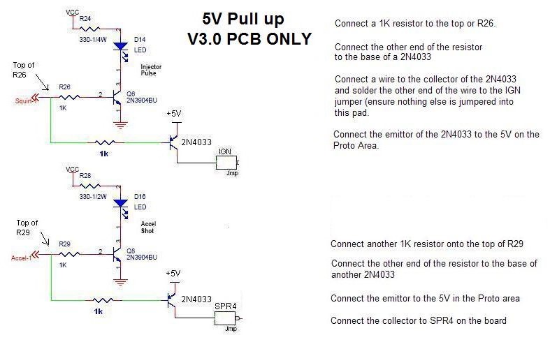
Try SPARK INVERTED = NO
to start with,
ensure you keep an eye on the temp of the COP when you first turn ignition
ON!!
If it gets hot try SPARK INVERTED = YES

Try SPARK INVERTED = NO
to start with,
ensure you keep an eye on the temp of the COP when you first turn ignition
ON!!
If it gets hot try SPARK INVERTED = YES
V3.0 PCB 5V pull up -- V2.2 PCB 5V pull up
V3.0 PCB Ground switching -- V2.2 PCB Ground switching
V3.0 PCB Schematics -- V2.2 PCB Schematics
V3.0 PCB Ground switching diagram
For a 4cy sequential setup you would need to have 4 of
these circuits rather than the 2 below, simply repeat the additions for
Spark C and D so
Spark C point to connect the 1K resistor is:
V3.0 PCB - Top of R27
V2.2 PCB - Right side of R26
Use SPR2 for the connection - Spark C will be on pin 4 of db37
Spark D point to connect the 1K resistor is
V3.0 PCB - Bottom of R1 with R1 removed
V2.2 PCB - Top of R14 R14 removed
Use SPR3 for the connection - Spark D will be on pin 5 of db37
Ground Switching
V3.0 PCB ONLY
Try SPARK INVERTED = NO
to start with,
ensure you keep an eye on the temp of the COP when you first turn ignition
ON!!
If it gets hot try SPARK INVERTED = YES
V2.2 PCB Ground switching diagram
Ground Switching
V2.2 PCB Only
Try SPARK INVERTED = NO
to start with,
ensure you keep an eye on the temp of the COP when you first turn ignition
ON!!
If it gets hot try SPARK INVERTED = YES
V3.0 PCB COP Schematic diagram

V2.2 PCB COP Schematic diagram

Driving two coils from the same spark output e.g. wasted spark coil on plug (COP)
In order to drive 2 coils from the same spark output, e.g. when you have 2 or 3 pinned COP's and want to run wasted spark, then the wiring is very similar to the multiple wiring, except that there are now 2 x VB921's per spark output. (See HERE for more on COPs before going this route)
Note: This db15 is NOT the same as the V3.57 PCB db15, that can be used but you would need to strengthen the copper traces on the PCB and you would need to select different pins to the ones shown is these instructions!!!!
Important note: One VB921 can only drive a single coil, do NOT wire 2 coils to one VB921.

Again it is recommended that you fit a db15 connector to the MS ECU in place of the LED's:

For 4cy sequential using coils that have no built in ignitor:

If
you have a question, comment, or suggestion for this FAQ, e-mail Phil
or James or post it on the forum.
No part of this manual may be reproduced or changed without written permission from Philip Ringwood, James Murray, Ken Culver and Lance.
Many thanks to Lance for giving us permission to edit and adapt his MS Manual for MSnS-Extra use.
©2004, 2005 Bruce Bowling and Al Grippo. All rights reserved.