MS2V3.0 Hardware Guide
Spark mode = "Basic Trigger"
Trigger angle/offset = 10 BTDC as a starting point, fine tune with a timing light.
Ignition capture = "Falling edge"
Spark output = "Going High"
Spark A output pin = "D14"
Dwell type = "Fixed duty"
Dwell duty = "50%"
6.4 GM HEI7
The original "High Energy Ignition" (HEI) distributors used the 4 pin module from the early 1970s is fine in the
breakerless distributor as designed, but is not suitable for computer timing control. The later 7 and 8 pin
modules and corresponding distributors are designed for computer control and should be an easy swap onto
earlier engines - not only are those modules intended for computer control, but their distributors are already
locked-out so no modifications are required. HEI7/8 uses three control wires to/from the Megasquirt.
The 'Ref' signal from the module to the Megasquirt gives rpm and engine position information.
The 'Est' signal from Megasquirt to the module controls the advance when running.
The 'Bypass' signal from Megasquirt to the module allows the module to beneficially control its own advance
during cranking. Once the engine has been running for more than 5 seconds, the Megasquirt takes control of
timing.
P = Positive from VR sensor
N = Negative from VR sensor
E = Electronic spark timing (EST) from Megasquirt IGN
R = Reference (REF) to Megasquirt Tach in
B = Bypass from Megasquirt bypass output (SPR3 shown)
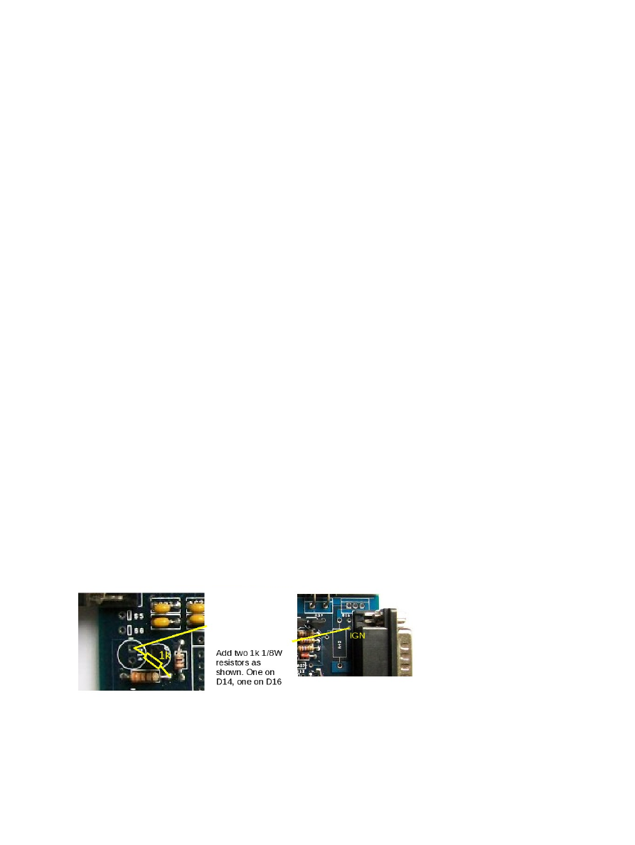
Set the mainboard as per section 5.2.4
Make the following modifications:
Add 1k 1/8W resistor from (-) of D14 to the right hand side of the resistor below.
Add 1k 1/8W resistor from (-) of D16 to the right hand side of the resistor below.
Jumper from (-) of D14 to IGN
Jumper from (-) of D16 to SPR3 (or your chosen pin)
(c) 2014-5 James Murray
2015-07-09
Page 109/201