MS2V3.0 Hardware Guide
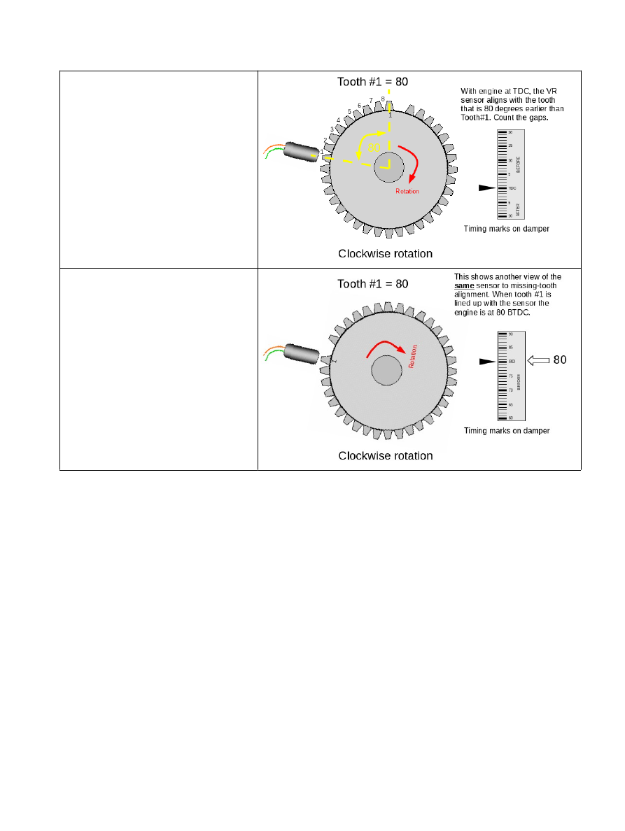
Clockwise rotation (normal) - method
a
Set your engine at TDC, then count the
number of GAPS to tooth#1 in the
direction of rotation (clockwise here) and
multiply by the angular size of the tooth.
e.g. 8 teeth * 10 deg/tooth = 80 deg
36-1 wheels are 10 deg per tooth
60-2 wheels are 6 deg per tooth
24-2 wheels are 15 deg per tooth
Clockwise rotation (normal) - method
b
A different way of looking at the SAME
phasing.
Turn your engine so that tooth #1 aligns
with the sensor.
Read off the tooth#1 angle from timing
marks/tape on the crank pulley.
Typical settings:
Spark mode = Toothed wheel
Trigger angle/offset = 0 (not used in toothed wheel mode)
Trigger wheel arrangement = Single wheel with missing tooth
Trigger wheel teeth = number of teeth including missing teeth (e.g. 36, 60 etc.)
Missing teeth = number of missing teeth (e.g. 1, 2)
Tooth #1 angle = tooth #1 angle as determined above
Main wheel speed = Crank wheel
Common combinations:
Ford 4 cyl = 36-1, 80deg tooth #1
Ford 6 cyl = 36-1, 50deg tooth #1
Ford 8 cyl = 36-1, 40deg tooth #1
Bosch 4 cyl (Peugeot, Vauxhall) = 60-2, 114 deg tooth #1
(c) 2014-5 James Murray
2015-07-09
Page 126/201