MS3X/V3.57 Hardware Guide
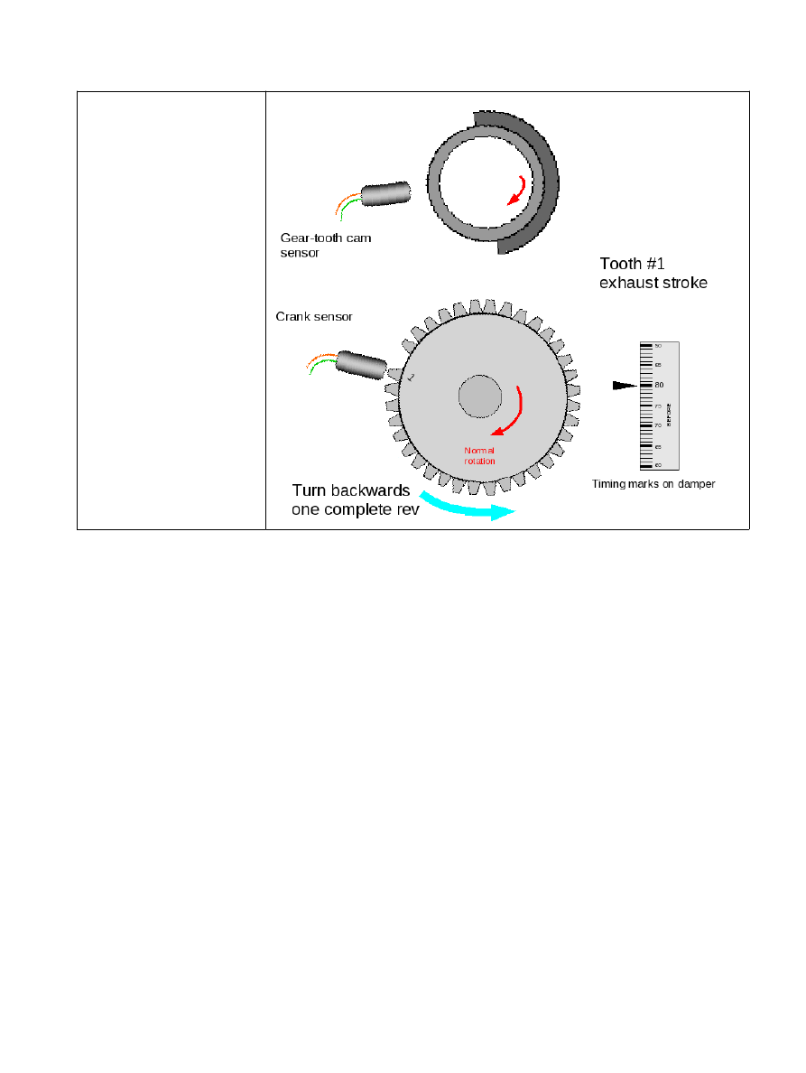
Now rotate the engine
backwards a full revolution.
The cam sensor will be
opposite that previous
window/tooth/vane. (If there
was a window before it must
be a vane now and vice-
versa.)
Typical settings:
Spark mode = Toothed wheel
Trigger angle/offset = 0 (not used in toothed wheel mode)
Trigger wheel arrangement = Dual wheel with missing tooth
Trigger wheel teeth = number of teeth including missing teeth (e.g. 36, 60 etc.)
Missing teeth = number of missing teeth (e.g. 1, 2)
Tooth #1 angle = tooth #1 angle as determined above
Main wheel speed = Crank wheel
Second trigger active on = Poll level
Level for phase one = as determined above
6.9.10 Nippondenso CAS
The Nippondenso CAS (crank angle sensor) comes in a number of versions which all use a 24 tooth main wheel
and a second wheel with one, two, three or four teeth. There is a single sensor (called Ne) pointing at the 24
tooth wheel and one (G1) or two (G1 and G2) sensors pointing at the second wheel.
This style of CAS is very common on Toyota and Mazda engine from the 1980s and 1990s.
The number of teeth on the second wheel determines whether it can be used (without modification) for single
coil distributor, wasted spark or coil-on-plug (COP) and sequential.
The version with a single tooth and two pickup sensors is intended for sequential. The two sensors are used by
the OEM to allow the engine to synchronize within one engine revolution. Presently we only support using one
of the 'G' sensors.
(c) 2014-6 James Murray
2016-11-13
Page 147/225