Using Microsquirt PWM signal to operate 4 wire IAC

All questions about MS2/Microsquirt/Microsquirt module. See also MS2/Extra manuals

Moderators: jsmcortina, muythaibxr

IslanderXJ
MS/Extra Newbie
Posts: 13
Joined: Thu Oct 25, 2012 5:03 pm

Using Microsquirt PWM signal to operate 4 wire IAC

Post by IslanderXJ »

OK, I'm a bit new to all of this so bear with me. If you see anything that doesn't jive, or I missed a step, fill me in.

I have a throttle body that has a built in 4 wire IAC, I'd really like to use it. No direct plug and play with the microsquirt.
Retrofitting a TRX700XX throttle body onto an XR650L for a fuel injection conversion. It's 95% theory at this point, the bike is torn down for a full rebuild and ground up reinforcement and modification.

I read through the whole Idle Air section of the Megasquirt Manual (found here ).
If we've figured this out later, and your reading it then, and you don't know how a stepper motor works, check this out:
http://www.freescale.com/files/microcon ... AN2974.pdf

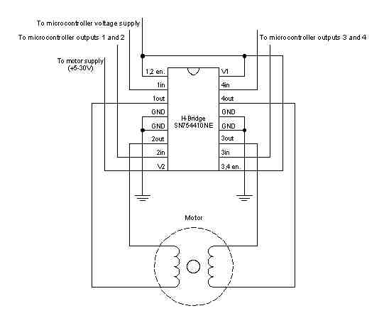
So, I've been dragging around the internet trying to find a way to turn the PWM signal into a 4-wire signal to operate basic H-bridge circuits that I "believe" the megasquirt boards would already have, but microsquirt does not (to save room?).

So I was thinking how do I translate PWM signal into something a little more usable. I googled my face off till I found this. All it needs is my PWM signal, 12vdc and a ground, and it will give me a variable 0-5vdc, sounds good to me!
Control an LM317T with a PWM signal

Now I have a 0-5vdc signal, it sounds more usable, but still not quite there yet... :RTFM:

I need to take that signal and turn it into something I can control those H-Bridge circuits with.

I found this which may solve another part of my predicament:
Adafruit Trinket - Mini Microcontroller - 5V Logic
Little bit of of code writing and a few beers and I think It could be used to translate a 0-5v signal to the 4 wire analog I need.

I know I'd need to take the signals from the above and step them up to whatever voltage the IAC required, I think a small transistor board would take care of that.

While I've got your attention. Anybody think there is enough room inside the microsquirt case to fit those tiny boards?
If not I'll just piggyback it on top of the housing. A picture of the case/housing opened up would be great.

I stumbled upon it when I found this:
Working 3D printed stepper motor
(I have no idea how I found it)
jsmcortina
Site Admin
Posts: 39619
Joined: Mon May 03, 2004 1:34 am
Location: Birmingham, UK
Contact:

Re: Using Microsquirt PWM signal to operate 4 wire IAC

Post by jsmcortina »

There's a bit more to it than that. Stepper motors require homing to a known position. Using just the PWM signal won't achieve that.

Sending you a PM with some other ideas too.

James
I can repair or upgrade Megasquirts in UK. http://www.jamesmurrayengineering.co.uk

My Success story: http://www.msextra.com/forums/viewtopic ... 04&t=34277
MSEXTRA documentation at: http://www.msextra.com/doc/index.html
New users, please read the "Forum Help Page".
IslanderXJ
MS/Extra Newbie
Posts: 13
Joined: Thu Oct 25, 2012 5:03 pm

Re: Using Microsquirt PWM signal to operate 4 wire IAC

Post by IslanderXJ »

jsmcortina wrote:There's a bit more to it than that. Stepper motors require homing to a known position. Using just the PWM signal won't achieve that.

Sending you a PM with some other ideas too.

James
Homing is just used to check the functionality of the IAC, or any stepper motor I believe. To make sure the the range of motion that the ECM is asking for is actually what it's doing. Since there's no feedback loop other than tach seeing the rpm and the ecm determining that the valve needs to open or close more.

In my brain (which is a weird place to begin with), I see the programming in the the Trinket(with the arduino software) translating the PWM duration or duty cycle into a open more or close more signal. Let's say it's closed and your just starting the engine, microsquirt(MS) asks for 100% duty cycle immediately, trinket programming translates to use the predetermined max number of steps to do that, opening the valve all the way. Engine is now running, cold, MS now asks for, lets say 70% and slowly declining (as the engine warms up, valve needs to close more till at "operating temp"), trinket translates that to start taking it down "steps" till its at 70% then continuing while matching what the MS is asking for.

As long as the Trinket can keep a running count of what step its on, I believe that would be sufficient to operate it? It would take a bit of trail and error on the front end to determine how many "steps" corresponded with what % duty cycle, after that it should run just like a standard megasquirt system? Heck, I was planning on reading through the megasquirt code as jumping off point to write the trinkets code.
hybrid
Super MS/Extra'er
Posts: 1275
Joined: Thu Apr 07, 2005 11:23 pm
Location: Sydney, Australia
Contact:

Re: Using Microsquirt PWM signal to operate 4 wire IAC

Post by hybrid »

What happens if the stepper is not at it's "zero" position when the engine is turned off?
Does the circuit just assume it's at zero each time?
Do not load someone elses tune and expect it to work for you!
Image
IslanderXJ
MS/Extra Newbie
Posts: 13
Joined: Thu Oct 25, 2012 5:03 pm

Re: Using Microsquirt PWM signal to operate 4 wire IAC

Post by IslanderXJ »

hybrid wrote:What happens if the stepper is not at it's "zero" position when the engine is turned off?
Does the circuit just assume it's at zero each time?
Any stepper controller without some kind of on-board memory would have the same problem.
I'm sure I'd have to program a shutdown "close" sequence in there to alleviate that.
Although for a fraction of a second there the PWM input would be 0% -> 0v -> close IAC valve
I might have to give the little board it own permanent power wire, same as a "keep alive".
dontz125
Super MS/Extra'er
Posts: 4228
Joined: Mon May 11, 2009 7:14 pm
Location: York, ON
Contact:

Re: Using Microsquirt PWM signal to operate 4 wire IAC

Post by dontz125 »

Memory doesn't work, as the valve could be bumped, removed, reset during power up, or any number of annoying things. That's why the first thing so many stepper controllers do is drive the moving element against a physical stop - it now knows exactly where the pintle / shaft etc is, and so can move it properly within the range.
Temporarily shut down - back soon!
QuadraMAP Sensor Module -- PWM-to-Stepper Controller -- Dual Coil Driver
Coming soon: OctoMAP Sensor Module
TTR Ignition Systems
IslanderXJ
MS/Extra Newbie
Posts: 13
Joined: Thu Oct 25, 2012 5:03 pm

Re: Using Microsquirt PWM signal to operate 4 wire IAC

Post by IslanderXJ »

dontz125 wrote:Memory doesn't work, as the valve could be bumped, removed, reset during power up, or any number of annoying things. That's why the first thing so many stepper controllers do is drive the moving element against a physical stop - it now knows exactly where the pintle / shaft etc is, and so can move it properly within the range.
Very true. Do you foresee any reason I can't do the same? Would you suggest closed or open?

The IAC stepper isn't big enough to hurt itself other than if I pulled it off the throttle body and it ran the valve pintle "closed" till it fell out.
dontz125
Super MS/Extra'er
Posts: 4228
Joined: Mon May 11, 2009 7:14 pm
Location: York, ON
Contact:

Re: Using Microsquirt PWM signal to operate 4 wire IAC

Post by dontz125 »

IslanderXJ wrote:Very true. Do you foresee any reason I can't do the same? Would you suggest closed or open?
Actually, I'm suggesting you do exactly that! The particular direction is up to you, but I think it's normally the opposite direction to the 'increasing' motion - if a valve starts fully open and closes with signal, you would run it open. If it starts fully closed and opens under signal, you would run it shut.
The IAC stepper isn't big enough to hurt itself other than if I pulled it off the throttle body and it ran the valve pintle "closed" till it fell out.
Operating any mechanical device with the cover / run-stops removed is a quick way to have parts fall off ... :lol:
Temporarily shut down - back soon!
QuadraMAP Sensor Module -- PWM-to-Stepper Controller -- Dual Coil Driver
Coming soon: OctoMAP Sensor Module
TTR Ignition Systems
IslanderXJ
MS/Extra Newbie
Posts: 13
Joined: Thu Oct 25, 2012 5:03 pm

Re: Using Microsquirt PWM signal to operate 4 wire IAC

Post by IslanderXJ »

dontz125 wrote:Actually, I'm suggesting you do exactly that! The particular direction is up to you, but I think it's normally the opposite direction to the 'increasing' motion - if a valve starts fully open and closes with signal, you would run it open. If it starts fully closed and opens under signal, you would run it shut.
At start up it opens all the way, then closes, so running it open it is!
dontz125 wrote:Operating any mechanical device with the cover / run-stops removed is a quick way to have parts fall off ... :lol:
Engineer buddy read this and immediately laughed and said "Self disassembling system, for very frequent inspection and servicing, ha ha" :lol:

Anyhoo...

Been doing some more :RTFM: and a lot of :? and :shock: going on.

Down to writing the arduino code to run the stepper motor. Mostly copy and pasting I expect, to be honest. I'm a mechanic/fabricator, not a programmer.

Dropped the LM317T and op-amps in general, too much stuff going on there. Also, it had a 1.25v ref jump so output would be 1.25v-6.25v, could only use 1.25v-5v, cutting down my voltage range too much to get the accuracy I wanted(might need) in the Trinket(and IAC).

Decided on a Low Pass Filter to take square wave PWM signal and filter it to varying 0-5v.
It's just a data/analog input at the Trinket pin (Board Pin#2 if your following that side of it), not actually driving anything significant, so no real amperage requirement there.

Using the following info:
[In MS2/Extra Settings] Valve Frequency Selection: 1.5kHz mode (more accurate) <--- proved to be incorrect, see James post below -EDIT-
That its a 0-5VDC signal
A small capacitor, lets 1uf
A common resistor, why not 10k ohms

Plug those values into this sweet RC Low-pass Filter Design for PWM Tool 8)

Should put out a pretty reliable voltage signal, less than .1VDC ripple with a settle time of about .02 seconds, pretty nice.

Using this analog input code (ignore the part about blinking and led - dumb) Analog Input
That gives me a workable number between 0 and 1023 which I can read within the code to drive the IAC to the correct open/close percentage.

Saying that, adafruit so kindly provided some cool pages in their "learning zone", Trinket (& Gemma) Servo Control. While that only runs a 3-wire servo via PWM output (which I found oddly amusing at this point), the input part of their code is useful for interpreting the 0-5vdc input from the Low Pass Filter to a number from 0 - 1023 based on its Analog Input function/code. Then taking that and using their Stepper Library Examples, plugging that into a SN7511ONE H-Bridge(pic below) were pretty close to having a functioning 4-Wire IAC using a microsquirt PWM Output!

:yeah!:

Image
Last edited by IslanderXJ on Tue Oct 29, 2013 3:58 am, edited 2 times in total.
IslanderXJ
MS/Extra Newbie
Posts: 13
Joined: Thu Oct 25, 2012 5:03 pm

Re: Using Microsquirt PWM signal to operate 4 wire IAC

Post by IslanderXJ »

Also, this is all small enough to be sunk into an old voltage regulator housing/heatsink and potted outside the microsquirt controller.


I just realized I made the assumption that the PWM signal operates at +5VDC, the MS2/Extra wiring diagram has it hooked up to 12vdc.
I never asked a question that is pretty important... :oops:
Can the FIDLE / PIN 7 on the microsquirt (which controls the signal via grounding it, not supplying power) operate at 5vdc? I was going to use the Vref Pin 28 if possible.
I can supply +12VDC to the stepper motor through the Dual H-Bridge, via V2 / PIN 8, so no problem actually moving the motor.
I have no idea how the microsquirt board operates internally... aaarrrggg. Back to digging around.

Image
The image says PIN 6, text says PIN 7, you should probably fix that...
jsmcortina
Site Admin
Posts: 39619
Joined: Mon May 03, 2004 1:34 am
Location: Birmingham, UK
Contact:

Re: Using Microsquirt PWM signal to operate 4 wire IAC

Post by jsmcortina »

IslanderXJ wrote:Using the following info:
[In MS2/Extra Settings] Valve Frequency Selection: 1.5kHz mode (more accurate)
That's actually least accurate. The idle PWM signal is generated in software. Anything about 78Hz loses precision.

James
I can repair or upgrade Megasquirts in UK. http://www.jamesmurrayengineering.co.uk

My Success story: http://www.msextra.com/forums/viewtopic ... 04&t=34277
MSEXTRA documentation at: http://www.msextra.com/doc/index.html
New users, please read the "Forum Help Page".
IslanderXJ
MS/Extra Newbie
Posts: 13
Joined: Thu Oct 25, 2012 5:03 pm

Re: Using Microsquirt PWM signal to operate 4 wire IAC

Post by IslanderXJ »

jsmcortina wrote:
IslanderXJ wrote:Using the following info:
[In MS2/Extra Settings] Valve Frequency Selection: 1.5kHz mode (more accurate)
That's actually least accurate. The idle PWM signal is generated in software. Anything about 78Hz loses precision.

James
So I shouldn't use higher than the 76Hz setting? Or did you mean 780Hz?
jsmcortina
Site Admin
Posts: 39619
Joined: Mon May 03, 2004 1:34 am
Location: Birmingham, UK
Contact:

Re: Using Microsquirt PWM signal to operate 4 wire IAC

Post by jsmcortina »

IslanderXJ wrote:
jsmcortina wrote:
IslanderXJ wrote:Using the following info:
[In MS2/Extra Settings] Valve Frequency Selection: 1.5kHz mode (more accurate)
That's actually least accurate. The idle PWM signal is generated in software. Anything about 78Hz loses precision.

James
So I shouldn't use higher than the 76Hz setting? Or did you mean 780Hz?
78Hz.
As noted, MS2 is using software to generate that PWM signal.
(MS3 uses a hardware PWM channel and has the same precision at all frequencies.)

James
I can repair or upgrade Megasquirts in UK. http://www.jamesmurrayengineering.co.uk

My Success story: http://www.msextra.com/forums/viewtopic ... 04&t=34277
MSEXTRA documentation at: http://www.msextra.com/doc/index.html
New users, please read the "Forum Help Page".
IslanderXJ
MS/Extra Newbie
Posts: 13
Joined: Thu Oct 25, 2012 5:03 pm

Re: Using Microsquirt PWM signal to operate 4 wire IAC

Post by IslanderXJ »

jsmcortina wrote:78Hz.
As noted, MS2 is using software to generate that PWM signal.
(MS3 uses a hardware PWM channel and has the same precision at all frequencies.)

James
Alright, good to know, thanks.

Do you know if that software can, or could be tweaked to, create a 0-5v PWM signal instead of the 0-12v PWM signal?
jsmcortina
Site Admin
Posts: 39619
Joined: Mon May 03, 2004 1:34 am
Location: Birmingham, UK
Contact:

Re: Using Microsquirt PWM signal to operate 4 wire IAC

Post by jsmcortina »

IslanderXJ wrote:Do you know if that software can, or could be tweaked to, create a 0-5v PWM signal instead of the 0-12v PWM signal?
That just depends on how you install a pullup resistor (your choice of 5V or 12V). As standard it uses a low-side open-collector style output.

James
I can repair or upgrade Megasquirts in UK. http://www.jamesmurrayengineering.co.uk

My Success story: http://www.msextra.com/forums/viewtopic ... 04&t=34277
MSEXTRA documentation at: http://www.msextra.com/doc/index.html
New users, please read the "Forum Help Page".
dontz125
Super MS/Extra'er
Posts: 4228
Joined: Mon May 11, 2009 7:14 pm
Location: York, ON
Contact:

Re: Using Microsquirt PWM signal to operate 4 wire IAC

Post by dontz125 »

Been doing some more :RTFM: and a lot of :? and :shock: going on.
No kidding! This is actually something I want to introduce into my product line-up, and I've been burning the Google wires for a week or two. I've come up with a circuit and PCB layout that I'm pretty happy with using a dinky little MC9S08 processor and a LV8548MC full-bridge driver; now it's just a matter of getting the time to go to prototype and testing ...
Temporarily shut down - back soon!
QuadraMAP Sensor Module -- PWM-to-Stepper Controller -- Dual Coil Driver
Coming soon: OctoMAP Sensor Module
TTR Ignition Systems
IslanderXJ
MS/Extra Newbie
Posts: 13
Joined: Thu Oct 25, 2012 5:03 pm

Re: Using Microsquirt PWM signal to operate 4 wire IAC

Post by IslanderXJ »

jsmcortina wrote:That just depends on how you install a pullup resistor (your choice of 5V or 12V). As standard it uses a low-side open-collector style output.

James
You say output, but the wire to the microsquirt controller is an input, that uses the ground side of the (PWM controlled) IAC to make the PWM signal, right? :?:
slow_hemi6
Super MS/Extra'er
Posts: 4122
Joined: Fri May 07, 2004 3:33 am
Location: Australia

Re: Using Microsquirt PWM signal to operate 4 wire IAC

Post by slow_hemi6 »

Why do the pwm to filter to adc? Wouldn't it be easier just to send the pwm to the micro and measure the high/low with a timer. The pics I was playing with a few years ago had a Capture,Compare,PWM module internally but the same could be implemented in most micro's.
Find the Manuals up top under Quick links: Manuals. :RTFM:
Cheers Luke
dontz125
Super MS/Extra'er
Posts: 4228
Joined: Mon May 11, 2009 7:14 pm
Location: York, ON
Contact:

Re: Using Microsquirt PWM signal to operate 4 wire IAC

Post by dontz125 »

IslanderXJ wrote:You say output, but the wire to the microsquirt controller is an input, that uses the ground side of the (PWM controlled) IAC to make the PWM signal, right? :?:
The wire going from the uS to your stepper controller is an input as far as the stepper controller is concerned, but an output from the uS point of view. The uS processor makes a MOSFET flicker on and off really fast; this can drive a PWM IAC directly, or (with a pull-up) create a PWM signal to drive your controller.

Slow_hemi - I have a design of my own in mind that takes the PWM signal straight from the uS, using the port internal pull-ups on the controller processor. It just occurs to me that I should probably add some sort of clamping riggin's, so an accidental short with a 12v wire doesn't pop the processor.
Temporarily shut down - back soon!
QuadraMAP Sensor Module -- PWM-to-Stepper Controller -- Dual Coil Driver
Coming soon: OctoMAP Sensor Module
TTR Ignition Systems
slow_hemi6
Super MS/Extra'er
Posts: 4122
Joined: Fri May 07, 2004 3:33 am
Location: Australia

Re: Using Microsquirt PWM signal to operate 4 wire IAC

Post by slow_hemi6 »

Years ago Masterx81 who still posts on here (saw one the other day) came up with a pic based PWM to stepper project that was working. It would be back in the MS1 extra development section somewhere.
Find the Manuals up top under Quick links: Manuals. :RTFM:
Cheers Luke
Post Reply