I suppose U7 (OpAmp) recives the adapted VR signal in the 3 pin input. Pin 2 is the another input used to adjust the hysterisis and voltage from the signal.
But U7 not only amplifies the signal right? It converts VR signal into a digital signal, is that correct?
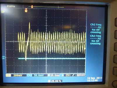
Yesterday I checked the signal in VRIN (correct) and TSEL (no signal), but forgot to check on U7's pin 3. But let's suppose I get a correct signal there (I'll check it this afternoon). Which is the problem? Or is that not a problem?
If R52-R56 pots are wrongly adjusted, U7 should give a signal?
Thanks!
SOLVED THIS, BUT I HAVE MORE PROBLEMS WHILE TRYING TO SYNC VR SIGNAL (see replies)