Since I am converting an air cooled engine I don't have a coolant sensor so am currently using a single CHT thermistor.
However, my plan is to fit 4 sensors (1 per cylinder) and run them to an Arduino. This will run a CHT gauge on the dash and average/normalise the 4 readings. I'd like to then send this to the MS but not sure how to do it. It must be possible as the JimStim etc. manage so what kind of signal should I send up the CLT/sensor GND wires?
How is CLT simulated?
Moderators: jsmcortina, muythaibxr
How is CLT simulated?
MicroSquirt V3 MS2/Extra release 3.2.1
Steyr-Puch Pinzgauer 710K
Steyr-Puch Pinzgauer 710K
-
jsmcortina
- Site Admin
- Posts: 39617
- Joined: Mon May 03, 2004 1:34 am
- Location: Birmingham, UK
- Contact:
Re: How is CLT simulated?
The stim uses a variable resistor, just like the thermistor it is simulating.
James
James
I can repair or upgrade Megasquirts in UK. http://www.jamesmurrayengineering.co.uk
My Success story: http://www.msextra.com/forums/viewtopic ... 04&t=34277
MSEXTRA documentation at: http://www.msextra.com/doc/index.html
New users, please read the "Forum Help Page".
My Success story: http://www.msextra.com/forums/viewtopic ... 04&t=34277
MSEXTRA documentation at: http://www.msextra.com/doc/index.html
New users, please read the "Forum Help Page".
How is CLT simulated?
Oh, is that manually turned (varied) then or is it something clever?
Could I disable the CLT input and use a PWM input instead?
Could I disable the CLT input and use a PWM input instead?
MicroSquirt V3 MS2/Extra release 3.2.1
Steyr-Puch Pinzgauer 710K
Steyr-Puch Pinzgauer 710K
-
jsmcortina
- Site Admin
- Posts: 39617
- Joined: Mon May 03, 2004 1:34 am
- Location: Birmingham, UK
- Contact:
Re: How is CLT simulated?
The schematic for the basic stim and for the coolant input circuit are both available online - please look at them.
James
James
I can repair or upgrade Megasquirts in UK. http://www.jamesmurrayengineering.co.uk
My Success story: http://www.msextra.com/forums/viewtopic ... 04&t=34277
MSEXTRA documentation at: http://www.msextra.com/doc/index.html
New users, please read the "Forum Help Page".
My Success story: http://www.msextra.com/forums/viewtopic ... 04&t=34277
MSEXTRA documentation at: http://www.msextra.com/doc/index.html
New users, please read the "Forum Help Page".
How is CLT simulated?
Thanks, James. I had a look and it showed that the CLT is used as a voltage divider but I'm new to electronics & am still confused. I'll try to work through the JimStim schematic and see if I can understand it
MicroSquirt V3 MS2/Extra release 3.2.1
Steyr-Puch Pinzgauer 710K
Steyr-Puch Pinzgauer 710K
How is CLT simulated?
Ah, OK, I see that it just uses manual potentiometers, might not be possible then
MicroSquirt V3 MS2/Extra release 3.2.1
Steyr-Puch Pinzgauer 710K
Steyr-Puch Pinzgauer 710K
-
SymTech Laboratories
- Super MS/Extra'er
- Posts: 2188
- Joined: Sun Aug 31, 2008 4:02 pm
- Location: South Florida, USA
- Contact:
Re: How is CLT simulated?
You could do that, but you would have to send the PWM signal through a low-pass filter and remove the bias resistor inside your MegaSquirt ECU (R7).spandit wrote:Could I disable the CLT input and use a PWM input instead?

How is CLT simulated?
I've got a MicroSquirt so can't really do that. I think what I meant to say was, can I set a PWM signal, generated from the Arduino, up as another sensor and use this for the warm up enrichment etc. instead of the CLT pin (to which I could just wire a fixed resistor)?
MicroSquirt V3 MS2/Extra release 3.2.1
Steyr-Puch Pinzgauer 710K
Steyr-Puch Pinzgauer 710K
-
racingmini_mtl
- Super MS/Extra'er
- Posts: 9130
- Joined: Sun May 02, 2004 6:51 am
- Location: Quebec, Canada
- Contact:
Re: How is CLT simulated?
No.spandit wrote:I've got a MicroSquirt so can't really do that. I think what I meant to say was, can I set a PWM signal, generated from the Arduino, up as another sensor and use this for the warm up enrichment etc. instead of the CLT pin (to which I could just wire a fixed resistor)?
Re: How is CLT simulated?
But couldn't he just put a voltage into the MS pin that normally would go to the sensor? If the voltage source were fairly low impedance (buffered with an opamp), the bias resistor would not have any effect. After all, the A/D is really just reading the voltage.
The toughest problem might be getting a "calibration curve" loaded, as it would have to be linear. So none of the standard thermistor curves would work, and neither would the curve generator in TS.
The toughest problem might be getting a "calibration curve" loaded, as it would have to be linear. So none of the standard thermistor curves would work, and neither would the curve generator in TS.
Eric Law
1990 Audi 80 quattro with AAN turbo engine: happily running on MS3+MS3X
2012 Audi A4 quattro, desperately in need of tweaking
Be alert! America needs more lerts.
1990 Audi 80 quattro with AAN turbo engine: happily running on MS3+MS3X
2012 Audi A4 quattro, desperately in need of tweaking
Be alert! America needs more lerts.
-
SymTech Laboratories
- Super MS/Extra'er
- Posts: 2188
- Joined: Sun Aug 31, 2008 4:02 pm
- Location: South Florida, USA
- Contact:
Re: How is CLT simulated?
That could work too. If the bias resistor had a much lower resistance (<100 ohms), it could complicate things. With an op-amp voltage follower, though, the standard resistor will have a negligible effect.elaw wrote:But couldn't he just put a voltage into the MS pin that normally would go to the sensor? If the voltage source were fairly low impedance (buffered with an opamp), the bias resistor would not have any effect. After all, the A/D is really just reading the voltage.
-
jsmcortina
- Site Admin
- Posts: 39617
- Joined: Mon May 03, 2004 1:34 am
- Location: Birmingham, UK
- Contact:
Re: How is CLT simulated?
Or how about a simple and reliable answer. Add a 5th temp sensor and use that for Megasquirt. Use the other four for your dash gauge project.
James
James
I can repair or upgrade Megasquirts in UK. http://www.jamesmurrayengineering.co.uk
My Success story: http://www.msextra.com/forums/viewtopic ... 04&t=34277
MSEXTRA documentation at: http://www.msextra.com/doc/index.html
New users, please read the "Forum Help Page".
My Success story: http://www.msextra.com/forums/viewtopic ... 04&t=34277
MSEXTRA documentation at: http://www.msextra.com/doc/index.html
New users, please read the "Forum Help Page".
How is CLT simulated?
Simple I likejsmcortina wrote:Or how about a simple and reliable answer. Add a 5th temp sensor and use that for Megasquirt. Use the other four for your dash gauge project.
James
Some good info above, though. Need to work out what the H most of it means. I know that MS uses a potential divider to measure the varying voltage obtained by having the thermistor in the circuit so thinking a filtered PWM output from the Arduino might have the same effect. I know the Arduino measures resistance in the same way (and has the same reference voltage).
Producing a curve isn't necessary as it will just be using data from the 4 sensors which all follow the same curve anyway.
Plenty of playing to do which keeps me off the streets!
MicroSquirt V3 MS2/Extra release 3.2.1
Steyr-Puch Pinzgauer 710K
Steyr-Puch Pinzgauer 710K
How is CLT simulated?
This is pretty much what I'm planning, although as per my note above, the curve isn't an issue (and even if it were, I could work it out algebraically)elaw wrote:But couldn't he just put a voltage into the MS pin that normally would go to the sensor? If the voltage source were fairly low impedance (buffered with an opamp), the bias resistor would not have any effect. After all, the A/D is really just reading the voltage.
The toughest problem might be getting a "calibration curve" loaded, as it would have to be linear. So none of the standard thermistor curves would work, and neither would the curve generator in TS.
Not sure what you mean about the op-amp stuff (new to electronics) but will read up on it
MicroSquirt V3 MS2/Extra release 3.2.1
Steyr-Puch Pinzgauer 710K
Steyr-Puch Pinzgauer 710K
How is CLT simulated?
About the only answer I've truly understood so far!racingmini_mtl wrote: No.
MicroSquirt V3 MS2/Extra release 3.2.1
Steyr-Puch Pinzgauer 710K
Steyr-Puch Pinzgauer 710K
Re: How is CLT simulated?
OK, using the voltage divider equation of Vout=Vin.(Z2/(Z1+Z2)) and taking the in-built bias resistor as Z1 (2490Ohms), I've constructed the following table, the Z2 values being drawn from the thermistor data table:
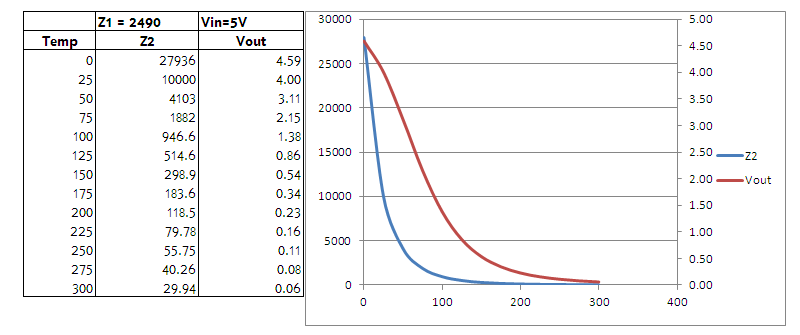
It would be fairly trivial to output a matching voltage from the Arduino (I think) from a PWM pin with a suitable filter. I think I'll just try it and see what happens
It would be fairly trivial to output a matching voltage from the Arduino (I think) from a PWM pin with a suitable filter. I think I'll just try it and see what happens
MicroSquirt V3 MS2/Extra release 3.2.1
Steyr-Puch Pinzgauer 710K
Steyr-Puch Pinzgauer 710K
-
SymTech Laboratories
- Super MS/Extra'er
- Posts: 2188
- Joined: Sun Aug 31, 2008 4:02 pm
- Location: South Florida, USA
- Contact:
Re: How is CLT simulated?
Give it a shot, you don't have anything to lose. The op-amp buffer is a must, though. Most electronics stores carry them. Here's the datasheet for the LM358, a relatively common op-amp, and a link to some information on using an op-amp as a voltage follower (buffer).spandit wrote:It would be fairly trivial to output a matching voltage from the Arduino (I think) from a PWM pin with a suitable filter. I think I'll just try it and see what happens
http://www.ti.com/lit/ds/symlink/lm158-n.pdf
http://en.wikipedia.org/wiki/Operationa ... plifier.29
How is CLT simulated?
Thanks. Have ordered a load of components and think there is an op-amp in there. Will try it without first and see what happens... 
MicroSquirt V3 MS2/Extra release 3.2.1
Steyr-Puch Pinzgauer 710K
Steyr-Puch Pinzgauer 710K
-
seishuku
- Experienced MS/Extra'er
- Posts: 209
- Joined: Tue Dec 01, 2009 5:38 pm
- Location: Wisconsin, USA
Re: How is CLT simulated?
Could use a digital potentiometer
http://datasheets.maximintegrated.com/en/ds/DS1267.pdf
http://datasheets.maximintegrated.com/en/ds/DS1267.pdf
-
SymTech Laboratories
- Super MS/Extra'er
- Posts: 2188
- Joined: Sun Aug 31, 2008 4:02 pm
- Location: South Florida, USA
- Contact:
Re: How is CLT simulated?
That might work if he calibrates the ECU with a linear and relatively narrow thermistor table, but he would have to use a 10-bit pot. In general, digital potentiometers don't have enough resolution to accurately emulate a thermistor.seishuku wrote:Could use a digital potentiometer
http://datasheets.maximintegrated.com/en/ds/DS1267.pdf