I thought about using a digital potentiometer but it seems pretty complex and anyway have tried it using other methods and so far the results are promising.
Tried it first with a normal potentiometer connected to the Arduino via a breadboard on VERY dodgy connections. The code was set up so that a proportional PWM signal was outputted. Connecting this output wire to the CLT pin on the MS and connecting the Arduino ground to sensor ground, the CLT needle could be wound up and down at will. I then tried through a low pass filter (I think!) and it seemed a little smoother. As proof of concept I think it's pretty successful and I'm sure with some tweaking of the Arduino code I could get some more sensible readings.
An advantage I have is that the CLT signal doesn't need to change very rapidly so I can set the output frequency to what I like (it currently takes 5 successive readings and calculates the average).
How is CLT simulated?
Moderators: jsmcortina, muythaibxr
Re: How is CLT simulated?
MicroSquirt V3 MS2/Extra release 3.2.1
Steyr-Puch Pinzgauer 710K
Steyr-Puch Pinzgauer 710K
-
SymTech Laboratories
- Super MS/Extra'er
- Posts: 2188
- Joined: Sun Aug 31, 2008 4:02 pm
- Location: South Florida, USA
- Contact:
Re: How is CLT simulated?
You may need to tweak your hardware too. We would be happy to help if you post a schematic. The "smoothness" of the signal out of RC low-pass filter depends on the frequency of the incoming signal, and the values of the resistor and capacitor.spandit wrote:Tried it first with a normal potentiometer connected to the Arduino via a breadboard on VERY dodgy connections. The code was set up so that a proportional PWM signal was outputted. Connecting this output wire to the CLT pin on the MS and connecting the Arduino ground to sensor ground, the CLT needle could be wound up and down at will. I then tried through a low pass filter (I think!) and it seemed a little smoother. As proof of concept I think it's pretty successful and I'm sure with some tweaking of the Arduino code I could get some more sensible readings.

How is CLT simulated?
I can't remember what frequency the Arduino pins operate at but with unfiltered PWM it seemed to work OK. I've a feeling the potentiometer I used was a logarithmic one - I've ordered some linear ones which should be a little more securely connected
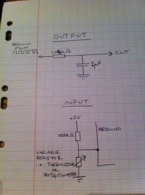
The schematic is only using the pot as a divider for the input and a resistor before the output with a 1uF cap going to ground for the filter - nothing complicated!
I've decided against constructing LED gauges for each sensor and will use a backlit LCD instead as it's far easier to wire up and can be used to display far more information
MicroSquirt V3 MS2/Extra release 3.2.1
Steyr-Puch Pinzgauer 710K
Steyr-Puch Pinzgauer 710K
-
SymTech Laboratories
- Super MS/Extra'er
- Posts: 2188
- Joined: Sun Aug 31, 2008 4:02 pm
- Location: South Florida, USA
- Contact:
Re: How is CLT simulated?
What value is the resistor? The potentiometer isn't necessary - it's just limiting the usable range of the PWM signal.spandit wrote:The schematic is only using the pot as a divider for the input and a resistor before the output with a 1uF cap going to ground for the filter - nothing complicated
Re: How is CLT simulated?
Ah, the potentiometer was wired in as I'm only simulating what the thermistor will be doing (i.e. having a variable resistance) - it was easier than wiring up a thermistor and dipping it into hot and cold water. I won't be using a pot in the finished "product"SymTech Laboratories wrote:What value is the resistor? The potentiometer isn't necessary - it's just limiting the usable range of the PWM signal.spandit wrote:The schematic is only using the pot as a divider for the input and a resistor before the output with a 1uF cap going to ground for the filter - nothing complicated
The input resistor is 100KOhm as this is what the thermistor tutorial specified, the output resistor is 10KOhm I have many other types. As I (hopefully) explained, this test today was just a proof of concept and none of the values are set in stone, so to speak.
Haven't tried it with an op-amp yet but doesn't look like I need to at the moment (just couldn't be bothered wiring it up as my breadboard is a nasty one and I was using stripped Cat5E cable as jumpers)
Here's the BIROCAD version:
and a short, crappy video showing that it kind of works...
MicroSquirt V3 MS2/Extra release 3.2.1
Steyr-Puch Pinzgauer 710K
Steyr-Puch Pinzgauer 710K
-
SymTech Laboratories
- Super MS/Extra'er
- Posts: 2188
- Joined: Sun Aug 31, 2008 4:02 pm
- Location: South Florida, USA
- Contact:
Re: How is CLT simulated?
From your original description, we thought you were using the potentiometer on the output. Using it to simulate a thermistor is perfectly okay!spandit wrote:Ah, the potentiometer was wired in as I'm only simulating what the thermistor will be doing (i.e. having a variable resistance) - it was easier than wiring up a thermistor and dipping it into hot and cold water. I won't be using a pot in the finished "product"
You'll ultimately need an op-amp. An RC filter doesn't have very low output impedance, so the bias resistor inside the MegaSquirt/MicroSquirt ECU will offset the signal and affect your working range.spandit wrote:Haven't tried it with an op-amp yet but doesn't look like I need to at the moment (just couldn't be bothered wiring it up as my breadboard is a nasty one and I was using stripped Cat5E cable as jumpers)
How is CLT simulated?
I shall take your advice and fit one! Pity I'm working tomorrow as want to get this thing built...You'll ultimately need an op-amp. An RC filter doesn't have very low output impedance, so the bias resistor inside the MegaSquirt/MicroSquirt ECU will offset the signal and affect your working range.
MicroSquirt V3 MS2/Extra release 3.2.1
Steyr-Puch Pinzgauer 710K
Steyr-Puch Pinzgauer 710K
Re: How is CLT simulated?
Had a play today with a better potentiometer and an op-amp. Didn't have any capacitors in the voltage follower circuit but the output from the Arduino had the filter installed on the output pin.
Results are promising - although not quite as expected. With the op-amp in the circuit, the CLT needle was quite unstable but with it out of the picture, the needle could be wound up and down quite smoothly (and was stable +- 1ºC when the potentiometer wasn't moved - considering this was on a flimsy breadboard that's not bad). I've taken video but frankly it's pretty boring and I can't be bothered to upload it.
I didn't try it with a raw PWM signal but I reckon it would probably work fine.
When I have a moment, I'll make up a better circuit board (Veroboard) and try again with 4 potentiometers, 1 to simulate each cylinder...
MicroSquirt V3 MS2/Extra release 3.2.1
Steyr-Puch Pinzgauer 710K
Steyr-Puch Pinzgauer 710K