How To - MS Onboard Bluetooth Cheap Ebay module (HC-05)
Posted: Tue Apr 18, 2017 6:44 am
Hello all.
This thread was a huge help when doing this, But i found the information disjointed and confusing sifting through so many posts, I'm hoping i can give everyone a rocksolid "how to" To get this working.
http://www.msextra.com/forums/viewtopic ... 22&t=43883
Ordering, Configuring and setting up the HC-05 Bluetooth unit for tuning the MS-ECU with Tuner studio.
Edit:
Note: The MS-ECU uses 5v Level TTL, while the HC-05 Uses 3.3V TTL. There have been zero failures as far as i know, and many people run these HC-05 off the MS-ECU's 5v TTL. My 2 devices are communicating with each other flawlessly so far. So i am not really sure how much of an issue this really is.
If anyone experiences any issues with Comms or the HC-05 failing outright, and you think it could be due to the TTL levels, please let us know. At the bottom of this guide is a quick top on a mod for a voltage divider, You can incorporate this into the 5v TTL (only the HC/05's RXD pin needs this mod) if you wish.
The risk is, the MS-ECU could possibly have coms issues triggering from a 3v level if it's looking for 5v. And the 5V from the MS-ECU could damage the input to the HC-05. But the devices have been communicating flawlessly to this point, and no one has reported any failures due to the 5v TTL, so I don't see any reason worth complicating the bluetooth mod. But I leave it up to you. See the bottom of this guide for a voltage divider mod to drop the 5v TTL to around 3.3v
/Edit.
You'll need 3 things to get this to work.
A USB-RS232 TTL converter
A HC-05 bluetooth unit
A terminal application
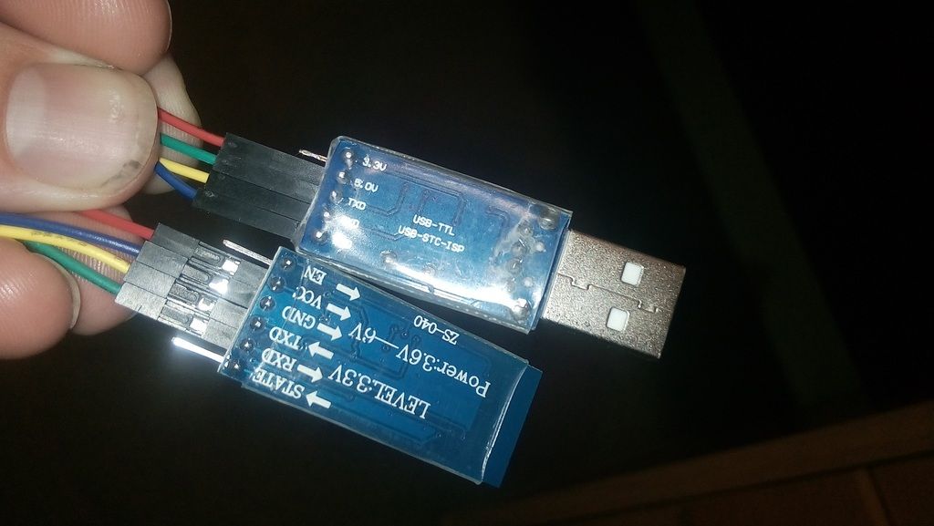
USB-RS232 TTL converter:
https://www.google.com.au/search?q=usb+ ... 82&bih=990
It's purpose is to emulate a serial com port. When you plug it into the computer and install the drivers it will operate as a RS232 over USB, It's intention is to be "Invisible" In other words the computer treats it as a normal serial port. It should (and i encourage you to check this) ouput TTL voltage level which is 3.3v on its RXD/TXD pins. This is important, The HC-05 will not communicate with a 5v or 12v serial connection.
There are several types available and to my knowledge they should all work as long as they are 3.3v (TTL) and have drivers, Some install automatically, some need the drivers downloaded form a 3rd party. I use a PL2303 (type that in ebay) based unit.
HC-05 Bluetooth module:
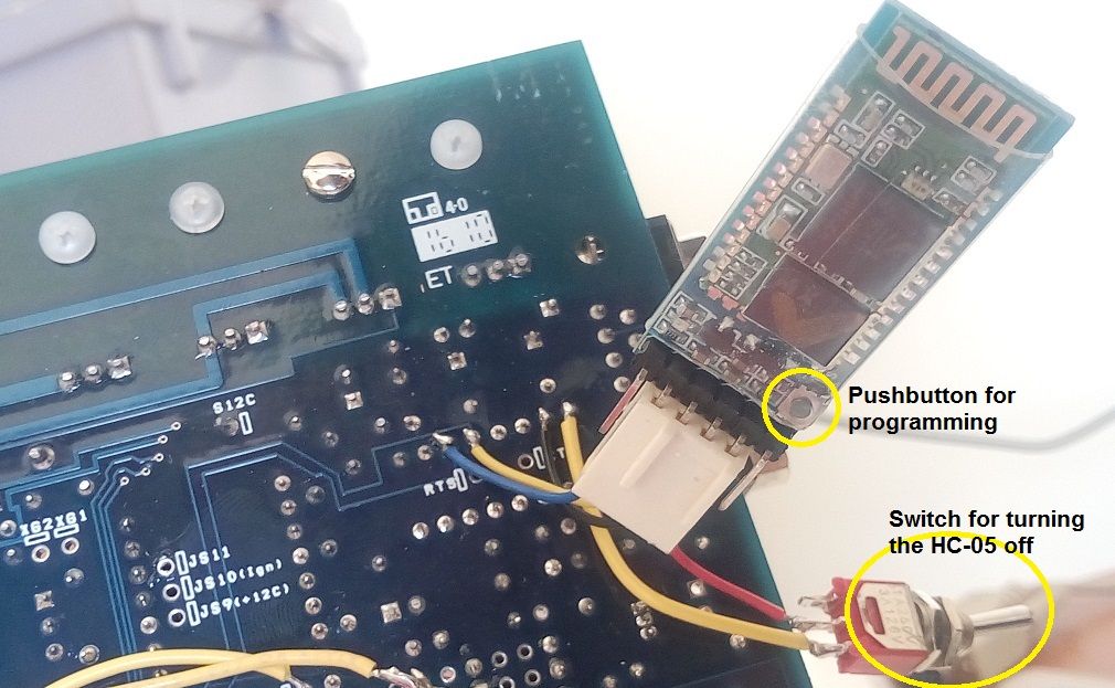
(search that on ebay, I recommend the one with the button like i got, circled in the pic above, as this makes programming easier)
These modules are designed to operate as an invisible serial link. Meaning when configured correctly, the computer and the connected device see a RS232 connection.
You put serial in one end, it communicates that over a blutooth connection. i recommend the HC-05 (http://www.ebay.com/sch/i.html?&_from=R ... _nkw=hc-05) as it can be configured to operate as a Master (seeks out and establishes bluetooth connections), Or a slave(passively awaits a connection attempt). They can be easily configured to different Baud rates to support MS1, or MS2. I'm assuming MS3 as well but I have not done this. Make sure you get HC-05 (type that in ebay) and I recommend getting the units that have the small tactile momentary switch (circled in the pic above) This switch makes programming the unit easier.
I recommend purchasing 2 of these units, You should be able to do it for under $15. Then you can configure a master and slave device, And establish a secure connection to the megasquirt in tuner studio in around 5 seconds after MS-ECU boot. That is not a joke, it's that fast!
A terminal application:
I use realterm: https://sourceforge.net/projects/realterm/
If you use this app, The first thing you should do is ensure the following is ALWAYS SET. (If you use any other application, you'll need to figure it out yourself)
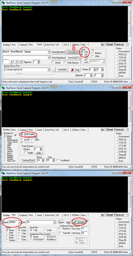
Display tab - Select half duplex (this shows what you type, otherwise you'll have no idea)
Port tab - Parity = None, Data bits = 8, Stop bits = 1, Hardware flow control = None, Baud = 38400 (this is the baud rate that the HC-05 will operate on when in programming mode), Port = Select the port your USB-RS232-TTL device is installed as. Then ensure you click the "change" button and check the detail on the bottom right match those you've just selected.
Send tab - In the "EOL" section ensure "CR" and "LF" are checked (this lets the HC-05 know when the command is finished, otherwise it will lock up and stop responding)
While in the "Send" tab, you will be typing your commands into the empty boxes on the left, And clicking "Send ASCII"
Setting up and programming the HC-05 via USB-TTL converter
Once you get your USB-TTL converter, Plug it into your PC. Ensure it installed correctly. If it does not, Find and update the drivers. Ensure it is installed and recognized as a COM device.
Once your happy it's installed, You can test you have everything set right. Get a jumper and connect the TTL converter's RXD and TXD pins together, creating a feedback loop. Then open your terminal program and test the connection. Make sure you have it set up as described above, and anything you send, Should be be echoed back. In the series of screens below, The first shows the successful feedback, In green is what i sent on TXD, and in yellow is what the TTL converter received on RXD. Hence, you've made a communication loop.
Now unplug the TTL converter and connect the HC-05 to the header pins on the back:
HC-05 <> USB-TTL
VCC <> 5v
Ground<>Ground
RX <>TX
TX <>RX
Programming the HC-05 to work with MS-ECU:
If you purchased the unit with the small tactile button, this is where you hold the button down. If not, you need to connect 5v to the "Key" header pin. If the breakout board does not have a Key header pine, you may be able to find a pinout for the HC-05 chip and sort it out that way.
While holding down the button, Plug the USB-TTL into the computer. The status led on the HC-05 will start to flash a 2 second on-off cycle/
Let the button go and launch your terminal application. Ensure the settings are correct. If using Realterm, set it up as instructed and get ready to send the following commands.
Note:
When setting the blutooth name, you will not be able to confirm it. If you send the "AT+NAME?" queary to the device, it will not reply with the name. This is a limitation with the HC-05 and is documented in it's manual. To confirm the name you need to unplug the USB-TTL and (Do NOT hold the button on the HC-05) plug it back in. The device should boot and start blinking quickly, showing it is in search mode. Wait a few seconds then search using a blutooth device (such as a mobile phone) to see if the HC-05 appears in the list of available bluetooth devices. The default name is "HC-05"
For MS1 set board speed to 9600, For MS2 set board speed to 115200
Set blutooth name and a password (for example "My fully sick car" and "1234")
Set to Slave
Note: Ensure all commands are entered in CAPITALS
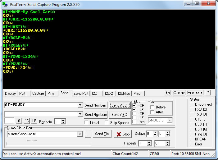
The commands are below, followed by a ">" and the expected reply from the HC-05.
AT > OK
AT+NAME=My Cool Car > OK (note: You cannot query the device name with a HC-05. It will reply with "OK" and you must just trust it has updated. You can only check later by searching for the device via bluetooth)
AT+UART=115200,0,0 > OK (Where "115200" you put the msecu's baud rate. 115200 for MS2 and 9600 for MS1)
AT+UART? > +UART=115200,0,0 > OK (this step confirms the current set baud speed. There will be 2 replys, the first gives the baud speed, the second is the acknowledgement "ok")
AT+ROLE=0 > OK (Setting role to 0=slave and 1=master, You want the MS-ECU's bluetooth to be a slave device)
AT+ROLE? > +ROLE=1 > OK (confirming the setting)
AT+PSWD=1234 > OK (Where "1234" you put the bluetooth password you want to protect the MS-ECU with)
AT+PSWD? > +PSWD=1234 > OK
More details on the HC-05 commands can be found here: http://eskimon.fr/wp-content/uploads/20 ... T_HC05.pdf
Follow the logic of the attached screenshot.
Now remove the HC-05 from the TTL device, Put it aside and mark it so you know it is to the MS-ECU device. We will call it the Slave.
Programming a second device to connect to the Megasquirt:
If you have a second HC-05, connect it to the TTL. We will be using this device as the Master You can skip this step for now, and come back to it after installing the 'Salve' HC-05 onto the MSECU.
Re enter programming mode and follow the logic you learned for the first device:
For MS1 set board speed to 9600 (for the Master, whatever you set the baud speed to, Tuner studio must also be set to, so it is easiest to set it to the same as you MSecu version)
For MS2 set board speed to 115200 (for the Master, whatever you set the baud speed to here, Tuner studio must also be set to, so it is easiest to set it to the same as you MSecu version)
Set to Master (AT+ROLE=1)
Set password, Use same password as before.
Set name (name can be anything, does not need to be same as before)
Your second HC-05 is now a dedicated MS-ECU communicator. Unplug it, and plug it back in (without holding the button) and it will boot into search mode.
Open Tuner studio and point it towards the COM port for the TTL device.
Installing the Slave HC-05 onto the MSECU V3.0 mainboard:
Now you need to get your hands dirty on the MSECU.
Get Your Slave HC-05. You need to solder it onto the board. It needs to go between the processor and the RS232 IC U6. Connect the following to the U6 IC on the MS board:
VCC <>Pin 16
Ground <>Pin 15
TX <> Pin 12
RX <> Pin 11
You should add a toggle switch to the VCC wire. So you can power down the bluetooth. You will need to power the bluetooth down to connect a serial connector to the DB9 on the megasquirt. This is needed to flash firmware, or if there is a problem with bluetooth.
You cannot and should not attempt to communicate with both DB9 and Bluetooth at the same time.
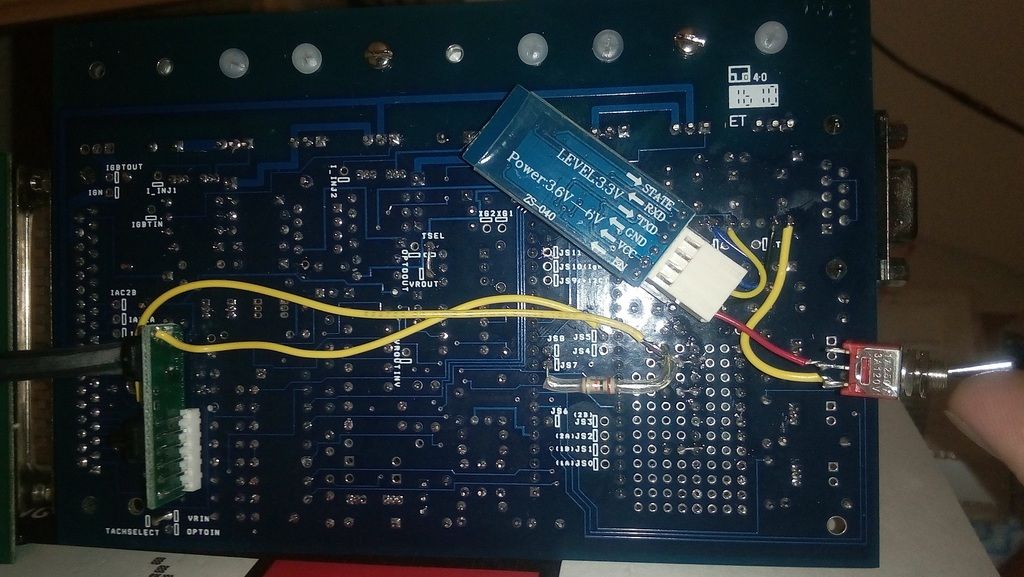
I recommend using the underside of the U6 chip directly, as showen in this pic, i used a 4 pin header connector I robbed off some other electronics, making it eazy for me to remove the HC-05 off the board if needed.

Now, power up the MS ecu.
If everything worked correctly, The master HC-05 (If it is still plugged into your computer and powered up?) will connect to the HC-05 slave in less than 5 seconds, and tuner studio will start communicating with the megasquirt.
If you don't have a second HC-05 setup, you can now search for the MS-ECU with your bluetooth laptop/phone and attempt to connect to it.
I hope this guide was eazy to follow and somewhat fool proof. Feedback is welcome!
EDIT:
ME-ECU 5v TTL Mod - Optional
Since the MS-ECU uses 5v TTL, and the HC-05 uses 3.3v TTL, Some people have expressed concerns that the HC-05 may fail due to the higher voltage on it's RXD pin. While no one could conform if this risk has ever eventuated in a failed unit, below is a simple fix to put your mind at ease if you choose.
This only needs to be carried out on the RXD pin of the HC-05.
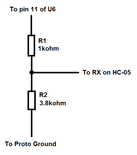
You will need a couple of resistors. We will be building a simple voltage divider. The goal is to get around 3.3v at the RDX pin. I used a 1kohm and a 3.9kohm which when checked with an oscilloscope, gave me 3.4v
To setup the circuit we will have 2 resistors. R1 and R2. You can use whatever 1/4w or 1/8w resistors you have kicking.
R1 should be somewhere between 1k and 10k.
R2 should be 3.5-3.9x the value of R1 (This is a figure i made up from testing. and should give you between 3.2-3.4v signal. This might not add up to 5v for those of you plugging this through ohms law, But remember the 5v TTL will be as close to the CPU's VCC as it can be, but it will not actually reach 5v.)
R1 connects on lead to pin 11 and the other to R2, R2's other lead then connects to Proto ground.
At the junction of R1 and R2, you connect RX from the HC-05
This is how i installed it on the board:
This thread was a huge help when doing this, But i found the information disjointed and confusing sifting through so many posts, I'm hoping i can give everyone a rocksolid "how to" To get this working.
http://www.msextra.com/forums/viewtopic ... 22&t=43883
Ordering, Configuring and setting up the HC-05 Bluetooth unit for tuning the MS-ECU with Tuner studio.
Edit:
Note: The MS-ECU uses 5v Level TTL, while the HC-05 Uses 3.3V TTL. There have been zero failures as far as i know, and many people run these HC-05 off the MS-ECU's 5v TTL. My 2 devices are communicating with each other flawlessly so far. So i am not really sure how much of an issue this really is.
If anyone experiences any issues with Comms or the HC-05 failing outright, and you think it could be due to the TTL levels, please let us know. At the bottom of this guide is a quick top on a mod for a voltage divider, You can incorporate this into the 5v TTL (only the HC/05's RXD pin needs this mod) if you wish.
The risk is, the MS-ECU could possibly have coms issues triggering from a 3v level if it's looking for 5v. And the 5V from the MS-ECU could damage the input to the HC-05. But the devices have been communicating flawlessly to this point, and no one has reported any failures due to the 5v TTL, so I don't see any reason worth complicating the bluetooth mod. But I leave it up to you. See the bottom of this guide for a voltage divider mod to drop the 5v TTL to around 3.3v
/Edit.
You'll need 3 things to get this to work.
A USB-RS232 TTL converter
A HC-05 bluetooth unit
A terminal application
USB-RS232 TTL converter:
https://www.google.com.au/search?q=usb+ ... 82&bih=990
It's purpose is to emulate a serial com port. When you plug it into the computer and install the drivers it will operate as a RS232 over USB, It's intention is to be "Invisible" In other words the computer treats it as a normal serial port. It should (and i encourage you to check this) ouput TTL voltage level which is 3.3v on its RXD/TXD pins. This is important, The HC-05 will not communicate with a 5v or 12v serial connection.
There are several types available and to my knowledge they should all work as long as they are 3.3v (TTL) and have drivers, Some install automatically, some need the drivers downloaded form a 3rd party. I use a PL2303 (type that in ebay) based unit.
HC-05 Bluetooth module:
(search that on ebay, I recommend the one with the button like i got, circled in the pic above, as this makes programming easier)
These modules are designed to operate as an invisible serial link. Meaning when configured correctly, the computer and the connected device see a RS232 connection.
You put serial in one end, it communicates that over a blutooth connection. i recommend the HC-05 (http://www.ebay.com/sch/i.html?&_from=R ... _nkw=hc-05) as it can be configured to operate as a Master (seeks out and establishes bluetooth connections), Or a slave(passively awaits a connection attempt). They can be easily configured to different Baud rates to support MS1, or MS2. I'm assuming MS3 as well but I have not done this. Make sure you get HC-05 (type that in ebay) and I recommend getting the units that have the small tactile momentary switch (circled in the pic above) This switch makes programming the unit easier.
I recommend purchasing 2 of these units, You should be able to do it for under $15. Then you can configure a master and slave device, And establish a secure connection to the megasquirt in tuner studio in around 5 seconds after MS-ECU boot. That is not a joke, it's that fast!
A terminal application:
I use realterm: https://sourceforge.net/projects/realterm/
If you use this app, The first thing you should do is ensure the following is ALWAYS SET. (If you use any other application, you'll need to figure it out yourself)
Display tab - Select half duplex (this shows what you type, otherwise you'll have no idea)
Port tab - Parity = None, Data bits = 8, Stop bits = 1, Hardware flow control = None, Baud = 38400 (this is the baud rate that the HC-05 will operate on when in programming mode), Port = Select the port your USB-RS232-TTL device is installed as. Then ensure you click the "change" button and check the detail on the bottom right match those you've just selected.
Send tab - In the "EOL" section ensure "CR" and "LF" are checked (this lets the HC-05 know when the command is finished, otherwise it will lock up and stop responding)
While in the "Send" tab, you will be typing your commands into the empty boxes on the left, And clicking "Send ASCII"
Setting up and programming the HC-05 via USB-TTL converter
Once you get your USB-TTL converter, Plug it into your PC. Ensure it installed correctly. If it does not, Find and update the drivers. Ensure it is installed and recognized as a COM device.
Once your happy it's installed, You can test you have everything set right. Get a jumper and connect the TTL converter's RXD and TXD pins together, creating a feedback loop. Then open your terminal program and test the connection. Make sure you have it set up as described above, and anything you send, Should be be echoed back. In the series of screens below, The first shows the successful feedback, In green is what i sent on TXD, and in yellow is what the TTL converter received on RXD. Hence, you've made a communication loop.
Now unplug the TTL converter and connect the HC-05 to the header pins on the back:
HC-05 <> USB-TTL
VCC <> 5v
Ground<>Ground
RX <>TX
TX <>RX
Programming the HC-05 to work with MS-ECU:
If you purchased the unit with the small tactile button, this is where you hold the button down. If not, you need to connect 5v to the "Key" header pin. If the breakout board does not have a Key header pine, you may be able to find a pinout for the HC-05 chip and sort it out that way.
While holding down the button, Plug the USB-TTL into the computer. The status led on the HC-05 will start to flash a 2 second on-off cycle/
Let the button go and launch your terminal application. Ensure the settings are correct. If using Realterm, set it up as instructed and get ready to send the following commands.
Note:
When setting the blutooth name, you will not be able to confirm it. If you send the "AT+NAME?" queary to the device, it will not reply with the name. This is a limitation with the HC-05 and is documented in it's manual. To confirm the name you need to unplug the USB-TTL and (Do NOT hold the button on the HC-05) plug it back in. The device should boot and start blinking quickly, showing it is in search mode. Wait a few seconds then search using a blutooth device (such as a mobile phone) to see if the HC-05 appears in the list of available bluetooth devices. The default name is "HC-05"
For MS1 set board speed to 9600, For MS2 set board speed to 115200
Set blutooth name and a password (for example "My fully sick car" and "1234")
Set to Slave
Note: Ensure all commands are entered in CAPITALS
The commands are below, followed by a ">" and the expected reply from the HC-05.
AT > OK
AT+NAME=My Cool Car > OK (note: You cannot query the device name with a HC-05. It will reply with "OK" and you must just trust it has updated. You can only check later by searching for the device via bluetooth)
AT+UART=115200,0,0 > OK (Where "115200" you put the msecu's baud rate. 115200 for MS2 and 9600 for MS1)
AT+UART? > +UART=115200,0,0 > OK (this step confirms the current set baud speed. There will be 2 replys, the first gives the baud speed, the second is the acknowledgement "ok")
AT+ROLE=0 > OK (Setting role to 0=slave and 1=master, You want the MS-ECU's bluetooth to be a slave device)
AT+ROLE? > +ROLE=1 > OK (confirming the setting)
AT+PSWD=1234 > OK (Where "1234" you put the bluetooth password you want to protect the MS-ECU with)
AT+PSWD? > +PSWD=1234 > OK
More details on the HC-05 commands can be found here: http://eskimon.fr/wp-content/uploads/20 ... T_HC05.pdf
Follow the logic of the attached screenshot.
Now remove the HC-05 from the TTL device, Put it aside and mark it so you know it is to the MS-ECU device. We will call it the Slave.
Programming a second device to connect to the Megasquirt:
If you have a second HC-05, connect it to the TTL. We will be using this device as the Master You can skip this step for now, and come back to it after installing the 'Salve' HC-05 onto the MSECU.
Re enter programming mode and follow the logic you learned for the first device:
For MS1 set board speed to 9600 (for the Master, whatever you set the baud speed to, Tuner studio must also be set to, so it is easiest to set it to the same as you MSecu version)
For MS2 set board speed to 115200 (for the Master, whatever you set the baud speed to here, Tuner studio must also be set to, so it is easiest to set it to the same as you MSecu version)
Set to Master (AT+ROLE=1)
Set password, Use same password as before.
Set name (name can be anything, does not need to be same as before)
Your second HC-05 is now a dedicated MS-ECU communicator. Unplug it, and plug it back in (without holding the button) and it will boot into search mode.
Open Tuner studio and point it towards the COM port for the TTL device.
Installing the Slave HC-05 onto the MSECU V3.0 mainboard:
Now you need to get your hands dirty on the MSECU.
Get Your Slave HC-05. You need to solder it onto the board. It needs to go between the processor and the RS232 IC U6. Connect the following to the U6 IC on the MS board:
VCC <>Pin 16
Ground <>Pin 15
TX <> Pin 12
RX <> Pin 11
You should add a toggle switch to the VCC wire. So you can power down the bluetooth. You will need to power the bluetooth down to connect a serial connector to the DB9 on the megasquirt. This is needed to flash firmware, or if there is a problem with bluetooth.
You cannot and should not attempt to communicate with both DB9 and Bluetooth at the same time.
I recommend using the underside of the U6 chip directly, as showen in this pic, i used a 4 pin header connector I robbed off some other electronics, making it eazy for me to remove the HC-05 off the board if needed.
Now, power up the MS ecu.
If everything worked correctly, The master HC-05 (If it is still plugged into your computer and powered up?) will connect to the HC-05 slave in less than 5 seconds, and tuner studio will start communicating with the megasquirt.
If you don't have a second HC-05 setup, you can now search for the MS-ECU with your bluetooth laptop/phone and attempt to connect to it.
I hope this guide was eazy to follow and somewhat fool proof. Feedback is welcome!
EDIT:
ME-ECU 5v TTL Mod - Optional
Since the MS-ECU uses 5v TTL, and the HC-05 uses 3.3v TTL, Some people have expressed concerns that the HC-05 may fail due to the higher voltage on it's RXD pin. While no one could conform if this risk has ever eventuated in a failed unit, below is a simple fix to put your mind at ease if you choose.
This only needs to be carried out on the RXD pin of the HC-05.
You will need a couple of resistors. We will be building a simple voltage divider. The goal is to get around 3.3v at the RDX pin. I used a 1kohm and a 3.9kohm which when checked with an oscilloscope, gave me 3.4v
To setup the circuit we will have 2 resistors. R1 and R2. You can use whatever 1/4w or 1/8w resistors you have kicking.
R1 should be somewhere between 1k and 10k.
R2 should be 3.5-3.9x the value of R1 (This is a figure i made up from testing. and should give you between 3.2-3.4v signal. This might not add up to 5v for those of you plugging this through ohms law, But remember the 5v TTL will be as close to the CPU's VCC as it can be, but it will not actually reach 5v.)
R1 connects on lead to pin 11 and the other to R2, R2's other lead then connects to Proto ground.
At the junction of R1 and R2, you connect RX from the HC-05
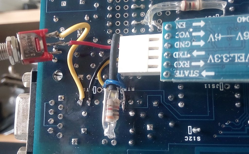
This is how i installed it on the board: