I have tested the Injector output and it seems to be working.
I am having a little trouble with the Ignition output and I was wondering if I could have some help please:
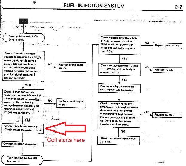
I am following this guide the best I can : https://www.diyautotune.com/support/tec ... -rx-turbo/
The EA82 turbo engine uses a single coil with a distributor for spark.
Unfortunately the guide doesnt go into detail about the board build details. When I built my board I set it up for a single coil high current output on D14 as I assumed that's would what be required to run the ignition.
I have the output set as going high and spark set to LEDs spark (Is that right, for just one output, there isnt an option for just one LED?)
Today when I ran the spark test in tunerstudio I got no spark.
I am beginning to wonder if I should be using a logic level output as the stock ECU outputs spark to a 'power transistor', not directly to the coil.
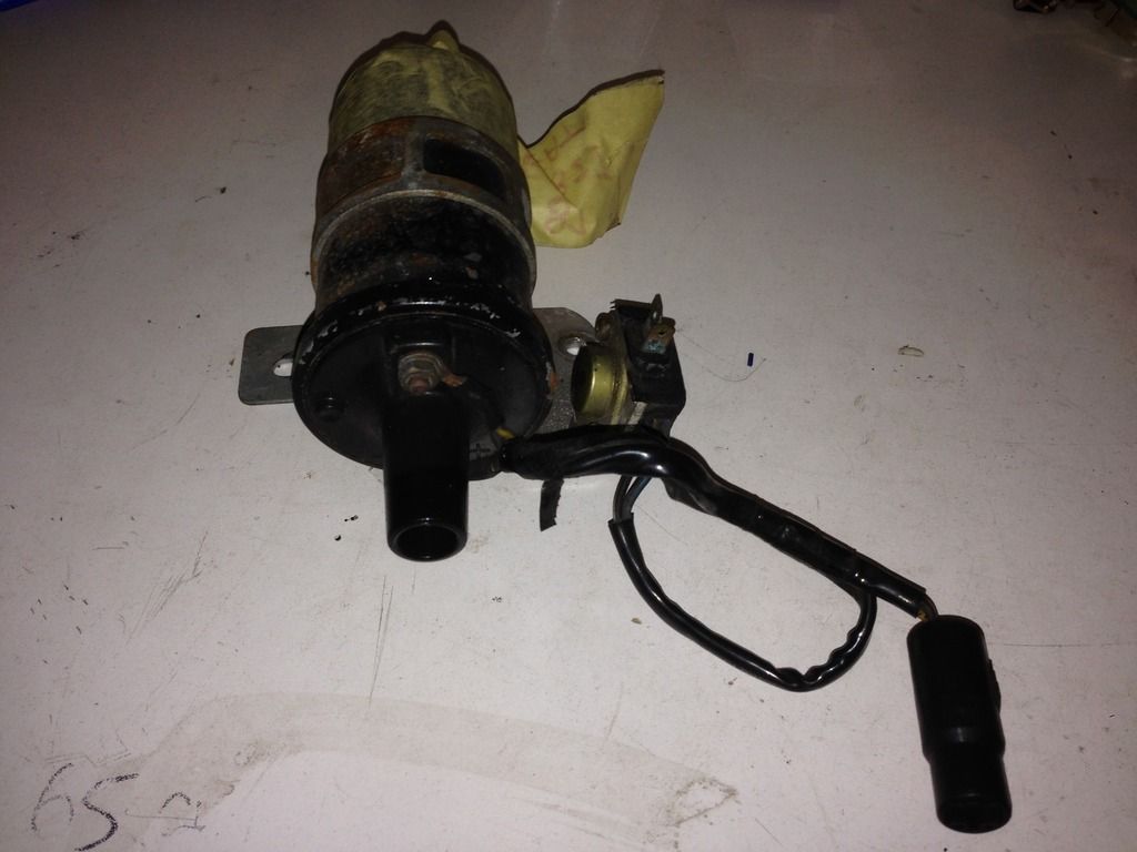
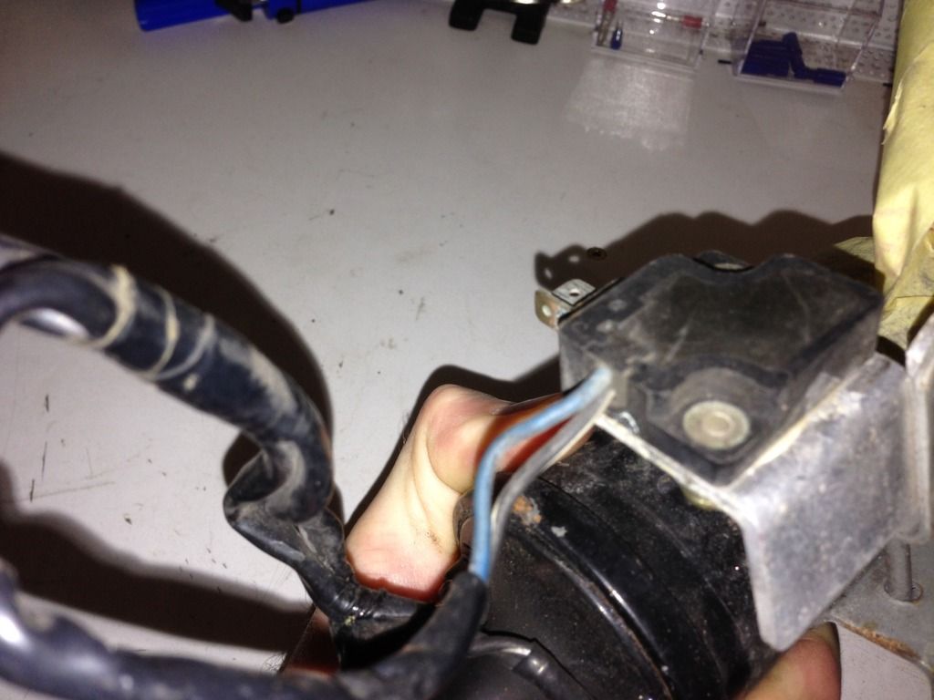
Here is a picture of the coil with the 'power transisitor" attached, is that a 1980's way of saying 'Ignitor'?
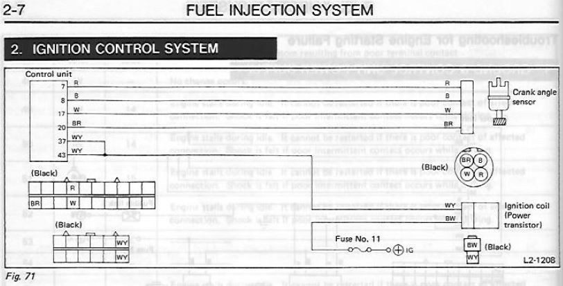
And the FSM schematic:
Thanks in advance for the help.