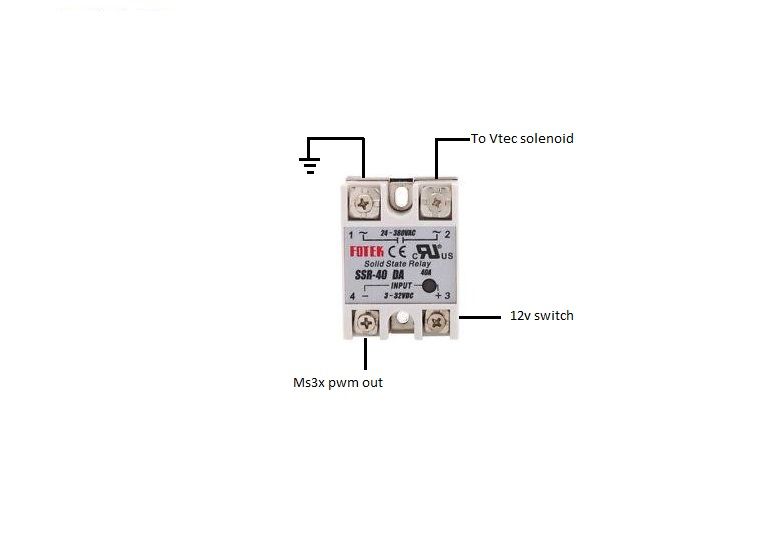
Hi guys i'm using this post to make sure i have this wiring correct before i actually try it on the car. I'm pretty much using the ssr for a Vtec solenoid. i have attached the diagram i made below, please let me know if this looks correct to you guys and if it isn't please let me know.
INCORRECT WAY
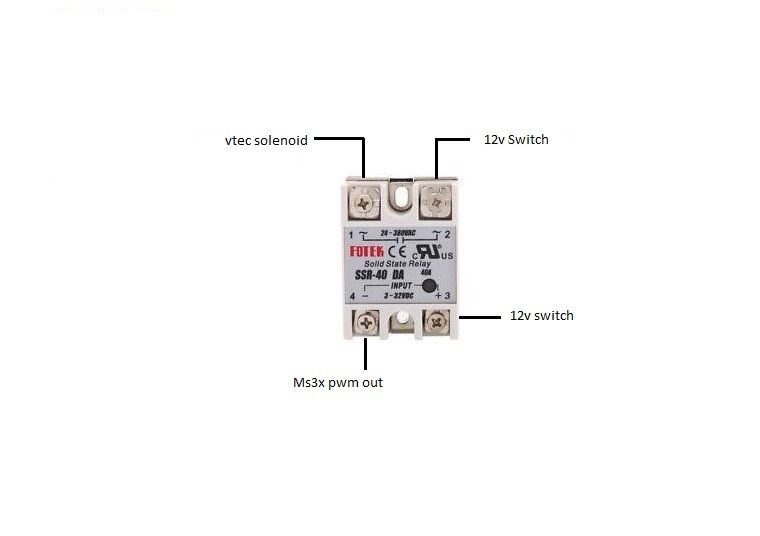
I know there are people that are wondering about the SSR relays as i did and i just decided to post a corrected version of the diagram so folks don't have to second guess it. I hope this help you guys out.
CORRECT WAY
Last edited by 3tc power on Thu Jul 19, 2018 11:19 pm, edited 1 time in total.
Yes, that looks OK, as long as the MS3X output you are using is a "sink"; and I think they all are.
Is the SSR you are using an AC relay as shown? That may be a problem with getting good PWM; in fact any SSR may be questionable, depending on the PWM frequency. I know, plenty of folks here are using SSRs for PWM; I'm just pointing out that an AC one, in particular, may not be providing a reliably "linear" control. That can be worked-around, but may cause some frustration because tuning tweaks don't work like they should seem to. I'll try to find a datasheet on that "Fotek" brand and see if there is anything obvious.
input current @ 12V is 7.5mA -- that shouldn't be a problem for the MS3X output you are using, but wouldn't hurt to verify
Load switching is "zero-crossing" -- that may be a big problem as your load never goes much below zero, you need the opinion of an SSR expert here...
Voltage drop on the load is 1.6V -- not a killer, but you are giving away about 10% of the drive voltage for your final device by using this 380VAC SSR
On/off time is "<10msec" -- how much less? These SSRs are intended for controlling 50/60 Hz power circuits, so PWM may be iffy past 60 Hz
Temp rating is 80C -- not a problem as long as it isn't in the engine compartment
I wouldn't suggest a mechanical relay for PWM. A DC SSR would be a better choice, and pick one for lower load operation (60VDC is probably most available). The best solution would be an FET or IGBT in a circuit that is designed for fast switching. I think there are electronics experts here that could provide info to do that fairly easy. Do you need 30-40A load switching? Maybe something as simple as a BIP373 could be used if your current needs are only 10-15A.
billr wrote:I wouldn't suggest a mechanical relay for PWM. A DC SSR would be a better choice, and pick one for lower load operation (60VDC is probably most available). The best solution would be an FET or IGBT in a circuit that is designed for fast switching. I think there are electronics experts here that could provide info to do that fairly easy. Do you need 30-40A load switching? Maybe something as simple as a BIP373 could be used if your current needs are only 10-15A.
I ordered a 25a 3-32v ssr dc to dc just in case, but that pic i use was just a reference to draw the diagram for my project write up. I'm thinking of mounting it in the cabin under the dash somewhere. thanks for all your input billr i really appreciate it. so my wiring is correct and the relay i ordered is should be ok and i also i got the heatsink for it. oh i'm using (F) injector bank on the ms3x programmable output for the vtec setup.
Billr is there anything else that you think i'm missing or this is all i would need for this setup?
What brand and P/N for the DC SSR? I could peek at the specs on that specific unit.
I'll ask again, more bluntly: Is this Vtec controlled with a direct-acting (mechanical) solenoid, or is it a solenoid valve acting on oil pressure? The MS3X drivers should be good by themselves for any decent solenoid valve.
billr wrote:What brand and P/N for the DC SSR? I could peek at the specs on that specific unit.
I'll ask again, more bluntly: Is this Vtec controlled with a direct-acting (mechanical) solenoid, or is it a solenoid valve acting on oil pressure? The MS3X drivers should be good by themselves for any decent solenoid valve.
Oil pressure... and the honda Vtec is triggered with 12v and is why i need a relay for this task. I hope this answers your questions
Last edited by 3tc power on Sat Apr 29, 2017 11:12 pm, edited 2 times in total.
thought I would update this, I got the solid state relay Wagner MGR-1 DD220D40. I connect terminal 1 to battery ground, terminal 2 to fan ground, terminal 3 to 12v+ and terminal 4 to PWM2 output. With no pullup I used 100hz and could control the fan from 10%dc to 100%dc based in coolant temp.
I got this from a post on your link. My question is why is terminal 2 going to the fan ground? Isn't a positive voltage coming from terminal 2 once the ms3 triggers terminal 4?
Well, the 12V is no problem. You are going to trigger the SSR from 12V anyway, right? What is the coil resistance or current draw of that Vtec solenoid?
Ah, it just occurred to me... maybe you are saying the Vtec solenoid has one terminal grounded and the 12V power to it is switched? I would do the trivial re-wiring to use the existing MS output, rather than an additional relay of any kind. Or, maybe you want to keep the wiring "all stock" so the OEM ECU can be revived at any time?
Hmm... no, another peek at your first post shows the SSR "grounding" the (Vtec) load. I still don't understand the need for any relay.
thought I would update this, I got the solid state relay Wagner MGR-1 DD220D40. I connect terminal 1 to battery ground, terminal 2 to fan ground, terminal 3 to 12v+ and terminal 4 to PWM2 output. With no pullup I used 100hz and could control the fan from 10%dc to 100%dc based in coolant temp.
I got this from a post on your link. My question is why is terminal 2 going to the fan ground? Isn't a positive voltage coming from terminal 2 once the ms3 triggers terminal 4?
It can be what you want. Typically the ground side is pwm'd, so I kept it that way. You can supply 12+ and pwm that if you wish. The two sides are separate, the load and trigger side never see each other
Volvo 940, 2jzge, MS3Pro, daily
240Z, 2JZ, MS3Pro boost control
billr wrote:Well, the 12V is no problem. You are going to trigger the SSR from 12V anyway, right? What is the coil resistance or current draw of that Vtec solenoid?
Ah, it just occurred to me... maybe you are saying the Vtec solenoid has one terminal grounded and the 12V power to it is switched? I would do the trivial re-wiring to use the existing MS output, rather than an additional relay of any kind. Or, maybe you want to keep the wiring "all stock" so the OEM ECU can be revived at any time?
Hmm... no, another peek at your first post shows the SSR "grounding" the (Vtec) load. I still don't understand the need for any relay.
Because from what i understand the vtec it activated by 12v and none of the ms3x out trigger 12v out to operate the selonoid.
Yes its a single wire and 12v is need for the Vtec to work. My whole reason behind this post it to figure out the correct wiring to use the pwm output to ground the relay to activate the ssr and get 12v out of the relay to the Vtec and
Last edited by 3tc power on Mon May 01, 2017 3:19 am, edited 1 time in total.
thought I would update this, I got the solid state relay Wagner MGR-1 DD220D40. I connect terminal 1 to battery ground, terminal 2 to fan ground, terminal 3 to 12v+ and terminal 4 to PWM2 output. With no pullup I used 100hz and could control the fan from 10%dc to 100%dc based in coolant temp.
I got this from a post on your link. My question is why is terminal 2 going to the fan ground? Isn't a positive voltage coming from terminal 2 once the ms3 triggers terminal 4?
It can be what you want. Typically the ground side is pwm'd, so I kept it that way. You can supply 12+ and pwm that if you wish. The two sides are separate, the load and trigger side never see each other
"Because from what i understand the vtec it activated by 12v and none of the ms3x out trigger 12v out to operate the selonoid.
Yes its a single wire and 12v is need for the Vtec to work. My whole reason behind this post it to figure out the correct wiring to use the pwm output to ground the relay to activate the ssr and get 12v out of the relay to the Vtec and"
We are going in circles here... if the Vtec coil has one terminal "always grounded" and the 12V to it needs to be switched, then the SSR connections shown in your first post won't work. That shows switching the ground, which the MS outputs can do by themselves. Again, assuming you don't really need 30-40A for a solenoid valve.
For what I now think you want, the SSR "load +" terminal must go to 12V, the "load -" term to the open term of Vtec solenoid, and the other Vtec term is (already) connected to ground.
billr wrote:"Because from what i understand the vtec it activated by 12v and none of the ms3x out trigger 12v out to operate the selonoid.
Yes its a single wire and 12v is need for the Vtec to work. My whole reason behind this post it to figure out the correct wiring to use the pwm output to ground the relay to activate the ssr and get 12v out of the relay to the Vtec and"
We are going in circles here... if the Vtec coil has one terminal "always grounded" and the 12V to it needs to be switched, then the SSR connections shown in your first post won't work. That shows switching the ground, which the MS outputs can do by themselves. Again, assuming you don't really need 30-40A for a solenoid valve.
For what I now think you want, the SSR "load +" terminal must go to 12V, the "load -" term to the open term of Vtec solenoid, and the other Vtec term is (already) connected to ground.
Lets do this another way. Ssr terminals 1,2,3and 4 what do i put to each terminal for its to get12v out to the selonoid like i was wiring it with a normal bosch relay?