I want to build a wiring diagram for my MS-project. Searched a lot, is there any template available? Is a lot of the same schematics..
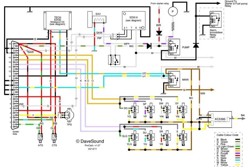
This is what i mean:
IMHO the trick is a balance between recognising each component and the minimum size - and being able to follow the wiring easily. And, of course, for your own use only, it's a matter of personal preference.
I use ProCAD+ and RISC OS - it's what I first used, and the devil you know...
Draftsight has some links to free libraries of symbols etc - but I haven't researched them. I just made my own as needed.
I dont know of a tool that creates "automotive" wiring diagrams. Most software aimed at electronic design, such as Eagle, assumes your schematic diagrams will lead to a PCB layout. There are are newer ones like KiCAD that do similar and I understand they are easier to use and stopping at the diagram is not a problem.
The devil you know is where I am. Been using TurboCAD for years now. It is a general purpose CAD tool - OK for anything from a house blueprint to a wiring diagram - but nowhere near as powerful as newer stuff - limited rendering, no checking, amateurish libraries. However I can create and edit drawings in my sleep with it and despite going a few rounds with much more modern tools, I find myself going back to it for general drafting work.
'Schematic capture' is what it's called. I could recommend various schematic capture packages I use for when I'm doing PCB design, but the trouble with these (as has already been pointed out) is that they are intended for PCB design and placing symbols involves working with selecting from (or defining new) library components, because what you're essentially doing is defining an underlying netlist and set of footprints, etc. The work and learning curve may be a little steep and not necessary considering all you want to do is draw a schematic.
What I recommend is you download Inkscape which is a completely free vector graphics application, kind of equivalent to Adobe Illustrator. It's available for Linux or Windows and I use it a hell of a lot (for example all of MSDroid's gauge graphics are created using it).
Trev16v wrote:'Schematic capture' is what it's called. I could recommend various schematic capture packages I use for when I'm doing PCB design, but the trouble with these (as has already been pointed out) is that they are intended for PCB design and placing symbols involves working with selecting from (or defining new) library components, because what you're essentially doing is defining an underlying netlist and set of footprints, etc. The work and learning curve may be a little steep and not necessary considering all you want to do is draw a schematic.
What I recommend is you download Inkscape which is a completely free vector graphics application, kind of equivalent to Adobe Illustrator. It's available for Linux or Windows and I use it a hell of a lot (for example all of MSDroid's gauge graphics are created using it).
Thanks! Also available for mac I see. Will download it. Are there electric symbol included, or should I google them?
You'd have to draw them yourself I'm afraid, unless you can find some readily drawn SVG electrical symbols online anywhere. It's a general vector graphics program so doesn't really have a library of symbols as such.
That's why I like ProCad+ so much. You can trace its linage back to the original Acorn !Draw which I first learned - and it doesn't have an intimidating number of facilities on screen, like so many others. But does have a very comprehensive library which is easy to add to. I like the idea of DraftSight, but don't find it anything like as intuitive to use. But as I said, the devil you know...