I want go from semi to full sequential by adding a single tooth cam signal to my existing 36-1 setup. This is a V8 and I am still using my distributor to distribute the spark. Before I go cut off 7 of the 8 teeth on my distributor I would like to know what RANGE of cam tooth angles are supported . I need to consider this along with rotor phasing and distributor clocking constraints.
Searching the MS3 docks I found:
http://www.msextra.com/doc/ms3/trigger- ... l#dualmiss
The above documentation simply states that the best cam tooth angle is 120 BTDC. Is there a bigger angle range that will still sync properly?
Specifics:
Ford V8
MS3 firmware 1.3.0
VR 36-1 crank trigger (80 degree #1 angle)
MS3x tacho > MSD > Distributor (Rotor phasing ~25deg BTDC)
MS3x INJ outs (running semi-seq)
Thanks for the help. I hope I can pull this off without having to modify the distributor itself.
Adding 1 tooth Cam signal to existing 36-1 Crank Setup
Moderators: jsmcortina, muythaibxr
-
chinhookmech
- MS/Extra Newbie
- Posts: 28
- Joined: Sun Jun 06, 2004 11:57 am
Re: Adding 1 tooth Cam signal to existing 36-1 Crank Setup
i think there is only one place that you DON'T want the cam sensor to happen and thats when the missing tooth event happens on the crank signal im pretty sure anywhere else should work fine the ideal is when the engine is approaching tdc compression on cylinder 1.
1990 bmw 320i daily driver with m20b25 ms3 sequential fuel, 380cc injectors, d585 coil near plug, home made cam sync, launch control, fan control, vss, homebrew egt logging what's next????
Re: Adding 1 tooth Cam signal to existing 36-1 Crank Setup
I'd have to check the manual again, but IIRC, you CAN even have the cam signal during the missing tooth gap. What you do have to be careful with is that the cam tooth is placed such that no amount of jitter, slop or slack can cause the cam signal edge to cross over the missing tooth signal edge; this will cause a loss of sync. For most arrangements, you have nearly 360 crank degrees of placement for the cam tooth.
The only reference I could find to "120 degrees" in the linked manual section was a comment in the Retrofit section that you normally want your #1 tooth in the 90-120deg range for a 4-cyl. This has nothing to do with the cam tooth angle.
The only reference I could find to "120 degrees" in the linked manual section was a comment in the Retrofit section that you normally want your #1 tooth in the 90-120deg range for a 4-cyl. This has nothing to do with the cam tooth angle.
Temporarily shut down - back soon!
QuadraMAP Sensor Module -- PWM-to-Stepper Controller -- Dual Coil Driver
Coming soon: OctoMAP Sensor Module
TTR Ignition Systems
QuadraMAP Sensor Module -- PWM-to-Stepper Controller -- Dual Coil Driver
Coming soon: OctoMAP Sensor Module
TTR Ignition Systems
-
chinhookmech
- MS/Extra Newbie
- Posts: 28
- Joined: Sun Jun 06, 2004 11:57 am
Re: Adding 1 tooth Cam signal to existing 36-1 Crank Setup
Where I found the 120 BTDC: 
If you look at the last phasing image in this http://www.msextra.com/doc/ms3/trigger- ... l#dualmiss section you will see the 120 BTDC on the dampner
or:

Current Hypothesis:
Based on the information presented I am now thinking as long as the cam tooth is in the 120 to 359 BTDC range it should work. All it should be doing is telling the ECU what half of the 720 degrees it is in.
Can anybody confirm or refute this?
If you look at the last phasing image in this http://www.msextra.com/doc/ms3/trigger- ... l#dualmiss section you will see the 120 BTDC on the dampner
or:
Current Hypothesis:
Based on the information presented I am now thinking as long as the cam tooth is in the 120 to 359 BTDC range it should work. All it should be doing is telling the ECU what half of the 720 degrees it is in.
Can anybody confirm or refute this?
Re: Adding 1 tooth Cam signal to existing 36-1 Crank Setup
You're reading too much into it. In the example, the crank #1 tooth is at 80deg BTDC; you then roll back to check the cam tooth placement. In this example, it's at 120 BTDC, but it's just that - an example. As far as engine operation is concerned, the actual cam tooth angle vs TDC is completely irrelevant. The crank angle between the #1 tooth and the cam tooth is similarly irrelevant, so long as there is no chance of the trigger edges overlapping. "Don't cross the streams."
The comment that "this is the best place for the cam tooth to pass the sensor" referred only to the fact that there was a nice, wide cushion between the crank tooth edge and the cam tooth edge. The fact that there is a 40deg span, or that the cam tooth is at 120 BTDC, has no bearing on anything.
The comment that "this is the best place for the cam tooth to pass the sensor" referred only to the fact that there was a nice, wide cushion between the crank tooth edge and the cam tooth edge. The fact that there is a 40deg span, or that the cam tooth is at 120 BTDC, has no bearing on anything.
Temporarily shut down - back soon!
QuadraMAP Sensor Module -- PWM-to-Stepper Controller -- Dual Coil Driver
Coming soon: OctoMAP Sensor Module
TTR Ignition Systems
QuadraMAP Sensor Module -- PWM-to-Stepper Controller -- Dual Coil Driver
Coming soon: OctoMAP Sensor Module
TTR Ignition Systems
-
chinhookmech
- MS/Extra Newbie
- Posts: 28
- Joined: Sun Jun 06, 2004 11:57 am
Re: Adding 1 tooth Cam signal to existing 36-1 Crank Setup
The documentation is vague in this case and the whole goal of this post is to get a clear quantitative spec. This way people know what constraints they are working with.
This is an example of a clear spec: (complete with allowed and disallowed angle ranges)
http://www.msextra.com/doc/ms3/distributor.html#phasein
Thanks guys, I have enough info to take a crack at it this weekend, with 8 teeth I should have one that gets me close to the "some more" (40 degrees) angle.
Re: Adding 1 tooth Cam signal to existing 36-1 Crank Setup
I would like to know where I connect the cam signal and separate crank signal on MS3x that also uses the MS relay board.
Hope you don't mind me adding this in here rather then starting a new post, but I thought your 'title' was very appropriate.
With all the reading I have confused myself with which pin this mini cam sync is to be connected to. Going off the MS manuals it says that the cam input is pin 32 for MS3x. In the manual I think they also call it a cam input, crank input and tach input.
Here they call it the 'cam tach' input http://www.msextra.com/doc/ms3/ignition.html#tachext
I thought the 'tach' input was the sensor off the crank. No wonder a bloke gets confused
Please Confirm - If I am now thinking right, I believe the Tach input from my crank angle sensor actually goes to the relay board Pin 15 being the Tach circuit and the mini cam sync goes to pin 32 on MS3x. This then leaves pin 26 on MS3x as the output to run my tacho (rev counter) on dash.
Have I got this right or am I a lost cause
Thanks, Kev
Last edited by Camo on Wed Aug 27, 2014 7:01 pm, edited 3 times in total.
-
piledriver
- Super MS/Extra'er
- Posts: 1681
- Joined: Tue Oct 27, 2009 6:24 am
- Location: Van Alstyne, Texas
Re: Adding 1 tooth Cam signal to existing 36-1 Crank Setup
The section you show is nice and clear, but the limitations may be quite specific to a basic trigger installation.
IIRC the trigger angles are essentially "free" if using a generic wheel type setup.
I'm sure one of the devs will appear and clarify any issues.
IIRC the trigger angles are essentially "free" if using a generic wheel type setup.
I'm sure one of the devs will appear and clarify any issues.
Always doing things the hard way, MS2 sequential w/ v1.01 mainboard, LS2 coils. 80 mile/day commuter status.
Re: Adding 1 tooth Cam signal to existing 36-1 Crank Setup
You are correct the cam signal goes to pin 32 on MS3X.
I am not using a relay board. Check for continuity between post 15 and pin 32 on the DB 37 connector.
If there is continuity then post 15 is correct.
http://www.msextra.com/doc/ms3/hardware.html#wiring
With a Ford engine you are in luck, there are two stock cam sensors available, use the one that fits the distributor hole on your block.
Re: Adding 1 tooth Cam signal to existing 36-1 Crank Setup
Hello,
I am posting here as I have a question very similar to the topic.
Assuming the example in the manual, 80° is tooth #1 angle and 120° is when the cam signal occurs, how is then MS configured? I mean do we have to tell the MS the angle of the cam tooth or it just waits for a cam signal and it internally knows the exact position of the cylinders?
It is not clear on my mind how the cam signal is configured in TS.
Miata NBFL 1.6 (EU), GT2560R, MS2Extra, Zeitronix.
Fiesta 1.25 Zetec-SE, N/A mods, MS3, AEM.
Fiesta 1.25 Zetec-SE, N/A mods, MS3, AEM.
-
jsmcortina
- Site Admin
- Posts: 39621
- Joined: Mon May 03, 2004 1:34 am
- Location: Birmingham, UK
- Contact:
Re: Adding 1 tooth Cam signal to existing 36-1 Crank Setup
The "crank" signal determines timing.
When the missing tooth region is reached the code checks "did we see a cam signal on this rev" (anywhere on the rev) and if it did then that's phase one, otherwise it is phase two.
James
When the missing tooth region is reached the code checks "did we see a cam signal on this rev" (anywhere on the rev) and if it did then that's phase one, otherwise it is phase two.
James
I can repair or upgrade Megasquirts in UK. http://www.jamesmurrayengineering.co.uk
My Success story: http://www.msextra.com/forums/viewtopic ... 04&t=34277
MSEXTRA documentation at: http://www.msextra.com/doc/index.html
New users, please read the "Forum Help Page".
My Success story: http://www.msextra.com/forums/viewtopic ... 04&t=34277
MSEXTRA documentation at: http://www.msextra.com/doc/index.html
New users, please read the "Forum Help Page".
Re: Adding 1 tooth Cam signal to existing 36-1 Crank Setup
So if I get this right you just have to configure TS like "Dual wheel with missing tooth" amd the ms does the rest for running sequential COPS and injection?
What about the "second trigger active on"? I don't quite understand that. Does it want to determing if the cam signal is active when the crank signal reaches (rising) or leaving (falling) a tooth on the crank wheel?
What about the "second trigger active on"? I don't quite understand that. Does it want to determing if the cam signal is active when the crank signal reaches (rising) or leaving (falling) a tooth on the crank wheel?
Miata NBFL 1.6 (EU), GT2560R, MS2Extra, Zeitronix.
Fiesta 1.25 Zetec-SE, N/A mods, MS3, AEM.
Fiesta 1.25 Zetec-SE, N/A mods, MS3, AEM.
Re: Adding 1 tooth Cam signal to existing 36-1 Crank Setup
I'm curious to see if op gets this to work. I've asked same question elsewhere. Would like to use my stock TFI dist as a cam sensor.
The posted cam sensor would work if he wasn't using the dist for spark.
The posted cam sensor would work if he wasn't using the dist for spark.
66 Mustang Turbo 6.0 LS on MS3X 80lb Deka injectors Tunerstudio Ultra and MS3 1.5.1
-
chinhookmech
- MS/Extra Newbie
- Posts: 28
- Joined: Sun Jun 06, 2004 11:57 am
Re: Adding 1 tooth Cam signal to existing 36-1 Crank Setup
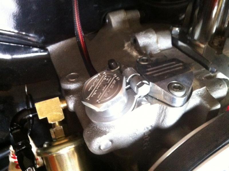
Sorry, no luck on getting this working last weekend. I ran into clearance issues between the cap and my new fuel rail setup. New fittings should be in before the end of the week.
Re: Adding 1 tooth Cam signal to existing 36-1 Crank Setup
Firstly, there is no correlation between post 15 on relay board (for crank sensor) and pin 32 MS3x board (for cam sensor). Thanks for trying, but I would be a little worried if I actually got continuity between these twoOllie8974 wrote:You are correct the cam signal goes to pin 32 on MS3X.
I am not using a relay board. Check for continuity between post 15 and pin 32 on the DB 37 connector.
If there is continuity then post 15 is correct.
Well I finally got to the point of setting up my ECU and I have no crank angle sensor signal or cam angle sensor signal. Not sure at this point where I have gone wrong.
Kev
-
piledriver
- Super MS/Extra'er
- Posts: 1681
- Joined: Tue Oct 27, 2009 6:24 am
- Location: Van Alstyne, Texas
Re: Adding 1 tooth Cam signal to existing 36-1 Crank Setup
Camo wrote:
Well I finally got to the point of setting up my ECU and I have no crank angle sensor signal or cam angle sensor signal. Not sure at this point where I have gone wrong.
Kev
If that's a pic of your motor, Marios cam sensor is a Hall type, and it may have a built in pullup.
If you are feeding it power and ground, it will switch that pullup to ground at some point, and you should be able to have someone twist the Minisync back and forth and you should be able to trace the signal with a DVM.
Assuming it has a pullup, remove the pullup jumper for the cam input on the MS3X.
(the instructions cover this)
If you have a hall crank sensor, you can do the same with a helper with a crecent wrench.
If you have his hidden VR sensor for the crank, use the cam sensor to provide a test signal.
You may just need to twiddle the gain pots on the MS3X and mainboard tho.
If you bought the setup from Mario, harass him, he likes it >;-)
Always doing things the hard way, MS2 sequential w/ v1.01 mainboard, LS2 coils. 80 mile/day commuter status.
Re: Adding 1 tooth Cam signal to existing 36-1 Crank Setup
Thanks Pile,
Yes my motor and Mario's cam sinc. I will have to ask him as my MS3x has the pullup installed at JP7 as per instructions and I never read about Mario's sync's possibly having a built in pullup. I will email him now and let you know what he says (when he replies - not sure of time over there
My crank is a VR sensor. Sorry (dummy here) can you expand your thoughts about using the cam sensor to test the VR senor of crank.
Will also look into the gain pots. I'm the type of bloke that follows instructions to a 'T" and if it says 3 turns I think it must be right
Cheers and thanks for the quick response.
Look out Mario, here I come
Kev
Re: Adding 1 tooth Cam signal to existing 36-1 Crank Setup
piledriver wrote:
If that's a pic of your motor, Marios cam sensor is a Hall type, and it may have a built in pullup.
Pile,
you were right
Also, I wasn't getting any crank readings in the Composite Logger of Tuner studio. Yet I recall seeing that when turning the motor with starter something about 90rpm. How would this happening if it wasn't picking any signals up ???? Maybe I have the VR cranks senor wiring arse about ????
Thanks again for your help, I'm sure you have helped hundreds on here and without people like you I'm sure many would give up.
Kev
-
piledriver
- Super MS/Extra'er
- Posts: 1681
- Joined: Tue Oct 27, 2009 6:24 am
- Location: Van Alstyne, Texas
Re: Adding 1 tooth Cam signal to existing 36-1 Crank Setup
I'm cheating, I helped beta test that setup for him.
Your starter should spin your motor at ~250-300 RPM.
Charge your battery--- a lot of weird happens with a not fully charged or otherwise gimpy battery.
Turn on the logging option for displaying the non interrupt data or somesuch.
Do try reversing the vr polarity. it only works right one way.
Statisticaly you have a 50/50 chance of hooking it up right, but Murphy wasn't a statistician.
Always doing things the hard way, MS2 sequential w/ v1.01 mainboard, LS2 coils. 80 mile/day commuter status.
Re: Adding 1 tooth Cam signal to existing 36-1 Crank Setup
So when I ran dual wheel crank/cam shared ECU my trigger angle was 27*jsmcortina wrote:The "crank" signal determines timing.
When the missing tooth region is reached the code checks "did we see a cam signal on this rev" (anywhere on the rev) and if it did then that's phase one, otherwise it is phase two.
James
then I went to 36-1 crank only wheel and my angle was 29.5*
NOW I just finished (so I thought) my MS3x re-wire for full sequential but I dind't know I would need a CAM sensor
Playing with the TS settings gave me the error and so I found this thread.
My question is, I read the the Cam tooth must not align with the 36-1 missing tooth, do my trigger angles above look like a conflict?
Am I asking a stupid question? I will have to Re-tap into the factory Cam sensor which originally gave me a 27* trigger angle.....
95 Probe v6-t MS1
00 Accent 2.0L-T,Ms1
14 Factory Five 818 MS2 4 ebc/meth only
03 Tiburon v6 SC 1st ever MS
93 Tracer KLDE,Compounds w/2 of everything, Twin Megasquirt ?
00 Lotus Esprit v8-TT Full MS3x/ls1 coils/water/Meth
97 200sx 1.6L Stock, MS2/3.0, Sequential, CBR1000r coils
00 Accent 2.0L-T,Ms1
14 Factory Five 818 MS2 4 ebc/meth only
03 Tiburon v6 SC 1st ever MS
93 Tracer KLDE,Compounds w/2 of everything, Twin Megasquirt ?
00 Lotus Esprit v8-TT Full MS3x/ls1 coils/water/Meth
97 200sx 1.6L Stock, MS2/3.0, Sequential, CBR1000r coils