5cyl 60-2+distributor cam sensor configuration questions

General support questions and announcements for MS3. See also MS3 manuals.

Moderators: jsmcortina, muythaibxr

Post Reply
2802NR
Helpful MS/Extra'er
Posts: 35
Joined: Tue Feb 14, 2006 10:03 am
Location: GJ, Colorado

5cyl 60-2+distributor cam sensor configuration questions

Post by 2802NR »

2014-09-14_14.32.52.msq
Just to start off I had this car (audi 5 cylinder 10vt) running and driving while triggered off a 5 window locked distributor. it is MS3 without the expansion triggering thru a single coil/distributor setup just recently added the crank trigger/cam sensor stuff.

so I finally got everything installed and wired in yesterday for my crank trigger hall sensor and a one window distributor being used as a cam sensor. I removed/changed the components and added jumpers as described here http://msextra.com/doc/general/tachin-v ... #spareopto and I configured MS as best as I could from what little 5cyl info I could find in the manual/here/and MSextra stuff.
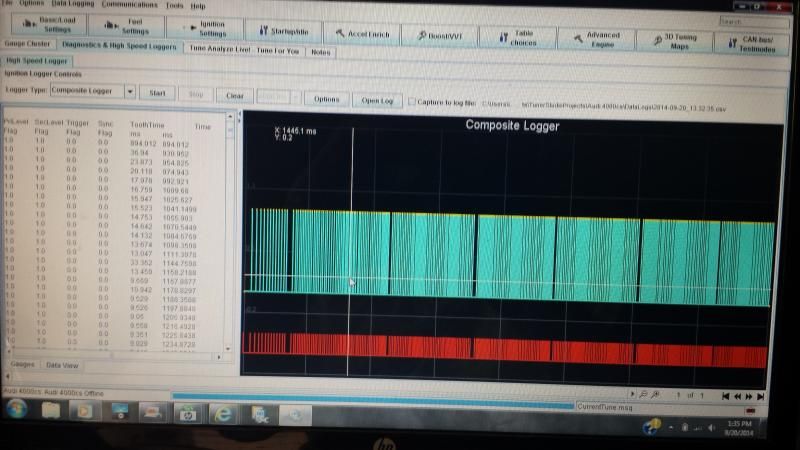
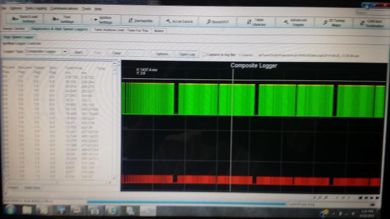
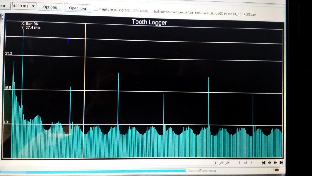
Now I am not seeing an RPM signal in megasquirt and I am relatively certain it has something to do with my configuration. I thought maybe if I posted a couple pics here someone might see a red flag in my setup. my crank signal seems to be getting thru according to the tooth logger but I still don't see any tach signal.
Image

when I found this write up: http://forums.turbobricks.com/showthread.php?t=126892

I noticed he said to describe it as a 120 tooth wheel but never touched on why or if I needed to then tell ms it is a cam wheel or if it was now 4 missing teeth. . . but once again its all old ms1 extra stuff and not easy to tell if it translates well into ms3

here is my ignition configuration, I have tried describing it as both a single wheel with missing teeth and a dual wheel missing teeth but I haven't tried the 120 tooth thing yet.
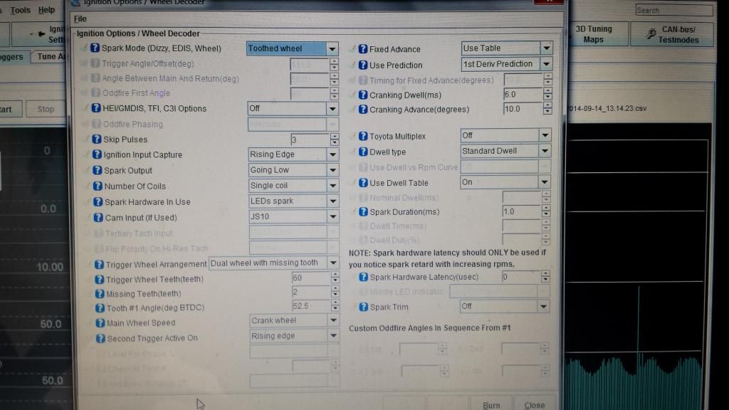
Image

just not sure what to try next and im not really sure how to tell if the cam signal is getting in at all. I sent the signal for it to IAC 2A since it wasn't being used. jumpered that to XG1 like the schematic says for the secondary cam sensor input. the only other thing I can think of, since mine is a 3.57 some of the 3.0 mod instructions are a little unclear. I jumpered JS2 which I believe to be optoout to JS10. . . could that be my mistake? wrong opto out maybe??
jsmcortina
Site Admin
Posts: 39619
Joined: Mon May 03, 2004 1:34 am
Location: Birmingham, UK
Contact:

Re: 5cyl 60-2+distributor cam sensor configuration questions

Post by jsmcortina »

See section 5.2.14 in the MS3base/V357 Hardware Manual.

James
I can repair or upgrade Megasquirts in UK. http://www.jamesmurrayengineering.co.uk

My Success story: http://www.msextra.com/forums/viewtopic ... 04&t=34277
MSEXTRA documentation at: http://www.msextra.com/doc/index.html
New users, please read the "Forum Help Page".
Paul_VR6
Super MS/Extra'er
Posts: 1978
Joined: Wed Apr 15, 2009 11:31 am
Location: Oxford, PA
Contact:

Re: 5cyl 60-2+distributor cam sensor configuration questions

Post by Paul_VR6 »

Describe your current cam trigger setup. You still on dizzy or cop? If the former use single wheel with missing and you should see rpm with no cam input.
-Paul
1992 Corrado SLC 3.6 VR6 11.38@120 - MS3 Pro Ultimate - Microsquirt I/O - Can EGT - Racepak IQ3s
kptuned.com - Megasquirting the World! Megasquirt Sales, Service, Tuning and More!
Image
racingmini_mtl
Super MS/Extra'er
Posts: 9130
Joined: Sun May 02, 2004 6:51 am
Location: Quebec, Canada
Contact:

Re: 5cyl 60-2+distributor cam sensor configuration questions

Post by racingmini_mtl »

Paul_VR6 wrote:Describe your current cam trigger setup. You still on dizzy or cop? If the former use single wheel with missing and you should see rpm with no cam input.
You can't have a crank-only signal with a 5-cylinder engine (or any odd-numbered engine).

You should take a composite log to see if the cam signal is actually registering.

Jean
jbperf.com Main site . . . . . . . . . . . . . . . . . . . . . . jbperf.com Forum
Image
2802NR
Helpful MS/Extra'er
Posts: 35
Joined: Tue Feb 14, 2006 10:03 am
Location: GJ, Colorado

Re: 5cyl 60-2+distributor cam sensor configuration questions

Post by 2802NR »

jsmcortina: thanks for that link. missed that one somehow. changed the ecu setup exactly as section describes but im still wondering a few things about my tuner studio configuration. gonna try logging it after dinner tonight.

Paul_vr6: description is in the first post. single coil distributor based. it needs the "cam sensor" because you cant run wasted spark on a 5 cylinder. the cam sensor is there for crank/cam phasing to tell the computer where TDC compression stroke is. I have already run into many "because 5 cylinder" scenarios and im sure im not out of the woods yet
2802NR
Helpful MS/Extra'er
Posts: 35
Joined: Tue Feb 14, 2006 10:03 am
Location: GJ, Colorado

Re: 5cyl 60-2+distributor cam sensor configuration questions

Post by 2802NR »

I made the changes needed in 5.2.14.3, im running my signal into IAC2A in the harness and IAC2A on the main board jumpered to JP1 pin 3. any chance that's a bad in/output to use for this? Im not using the IAC circuit for anything else and the only other jumpers I did were for the hall effect trigger, both my sensors being hall I left all that alone

did a composite log and its still not seeing any cam signal
2802NR
Helpful MS/Extra'er
Posts: 35
Joined: Tue Feb 14, 2006 10:03 am
Location: GJ, Colorado

Re: 5cyl 60-2+distributor cam sensor configuration questions

Post by 2802NR »

I checked a few things today, good power and ground at the sensor, good continuity on the signal wire from the sensor to the db37. I even switched from using IAC2A to SPR4 just incase that was a bad input to use. double checked all the steps called for in the manual 5.2.14.3 still no signal. the only other thought I had was do I need to jumper from the spr4 pad on the board to the pin itself?

what am I missing here?? do I need to remove jumpers previously installed for the hall opto input? I just don't know what else to try at this point without an oscilloscope
2802NR
Helpful MS/Extra'er
Posts: 35
Joined: Tue Feb 14, 2006 10:03 am
Location: GJ, Colorado

Re: 5cyl 60-2+distributor cam sensor configuration questions

Post by 2802NR »

here is my composite log with jumper JP1 - JP2 installed
Image

and here is my composite log with jumper JP2 - JP3 installed out of curiosity
Image

am I missing a jumper from JP3 to somewhere that isn't covered in the manual? seems the signal is making it that far atleast.
Paul_VR6
Super MS/Extra'er
Posts: 1978
Joined: Wed Apr 15, 2009 11:31 am
Location: Oxford, PA
Contact:

Re: 5cyl 60-2+distributor cam sensor configuration questions

Post by Paul_VR6 »

You need to be using the vr circuit for crank and the opto or direct wiring for the hall.

What wire/pin is the cam coming in on and exactly where does it go on the board after?

Ps: sorry about the bad advice, read the title as 6cyl
-Paul
1992 Corrado SLC 3.6 VR6 11.38@120 - MS3 Pro Ultimate - Microsquirt I/O - Can EGT - Racepak IQ3s
kptuned.com - Megasquirting the World! Megasquirt Sales, Service, Tuning and More!
Image
2802NR
Helpful MS/Extra'er
Posts: 35
Joined: Tue Feb 14, 2006 10:03 am
Location: GJ, Colorado

Re: 5cyl 60-2+distributor cam sensor configuration questions

Post by 2802NR »

no problem. the input is going from the sensor to spr4 in the DIY harness (pin 6) and from there its jumpered to JP3 as it says to do in the ms3base/3.57 manual.
Paul_VR6
Super MS/Extra'er
Posts: 1978
Joined: Wed Apr 15, 2009 11:31 am
Location: Oxford, PA
Contact:

Re: 5cyl 60-2+distributor cam sensor configuration questions

Post by Paul_VR6 »

J1/1 to js10?
-Paul
1992 Corrado SLC 3.6 VR6 11.38@120 - MS3 Pro Ultimate - Microsquirt I/O - Can EGT - Racepak IQ3s
kptuned.com - Megasquirting the World! Megasquirt Sales, Service, Tuning and More!
Image
2802NR
Helpful MS/Extra'er
Posts: 35
Joined: Tue Feb 14, 2006 10:03 am
Location: GJ, Colorado

Re: 5cyl 60-2+distributor cam sensor configuration questions

Post by 2802NR »

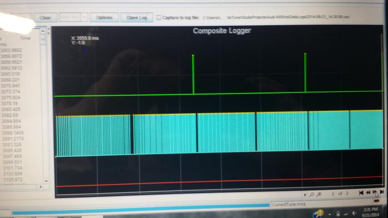
got it figured out yesterday. I was under the impression that the bosch hall was a 0-5v signal when it is actually a switch to ground. once I added the +5v/470r pullup resistor it fired right up. here is a composite log of that "first try" :lol:
Image
Post Reply