Dead time vs volts curve interpolation

General support questions and announcements for MS3. See also MS3 manuals.

Moderators: jsmcortina, muythaibxr

9secz
Experienced MS/Extra'er
Posts: 204
Joined: Sun Jun 13, 2010 10:33 am
Location: NorCal USA
Contact:

Dead time vs volts curve interpolation

Post by 9secz »

I flow benched a set of low impedance 750 cc injectors. Four of the 6 injectors had a bump in the curve at 13.2V as shown in this Excel chart.

Image

The dead time correction curves allow only 6 entries as shown on the right side of the screen shot below.

Image

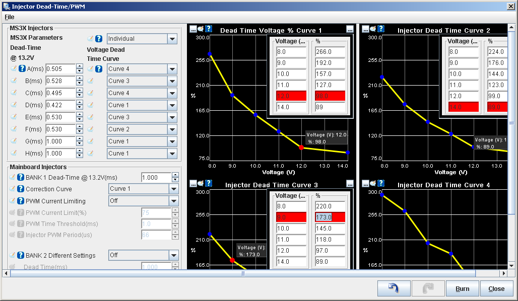
Since there are only 6 table cells, I figured I would skip an entry for 13.2 because that is captured in the dead time @ 13.2 table as shown on the left side of the screen shot above.

But I'm wondering if the entered dead time for 13.2 will be used as an interpolation end point, or if the code will interpolate between the 12V and 14V entries in the correction curves.

This is a concern because my MS3 reports that the operating voltage is in the 13.2V neighborhood most of the time.

So, does the code use the dead time @ 13.2 table for interpolation, or does it use only the values from the curves?

If you're curious, this is a vid of my injector test bench.

https://www.youtube.com/watch?v=KlnS67s8aGQ

Jeff
9secz
Experienced MS/Extra'er
Posts: 204
Joined: Sun Jun 13, 2010 10:33 am
Location: NorCal USA
Contact:

Re: Dead time vs volts curve interpolation

Post by 9secz »

Does anybody know if 13.2 V is used as an interpolation end point?

Jeff
9secz
Experienced MS/Extra'er
Posts: 204
Joined: Sun Jun 13, 2010 10:33 am
Location: NorCal USA
Contact:

Re: Dead time vs volts curve interpolation

Post by 9secz »

C'mon guys! I asked nice and provided all the data. Surely somebody here knows how the code does dead time interpolation.

Cue Lesley Neilson

http://jeffstevens.org/CarPics/Noble/Shirley.mp3

Jeff
kaeman
Master MS/Extra'er
Posts: 643
Joined: Sun Nov 06, 2005 12:31 am
Location: NORTHERN CALIFORNIA

Re: Dead time vs volts curve interpolation

Post by kaeman »

the code will use the voltage reading determined by megasquirt and then compare it to the values you entered in the curves to make the corrections, and it will interpolate data as it does in all the other tables and curves it uses. the 13.2 volt reading is just a common voltage to take readings at(fully charged battery). I think the only way you could make it use 13.2 volts as an endpoint would be to delete all the data in the curve above 13.2 volts... I still don't know if you could forve it to stop interpolating the higher voltages....


Good Luck.
64 el camino, 383 SBC, 11.7 to1 CR, accufab tb/rhs intake, 44lb injectors, trick flow heads, xr292r solid roller cam, belt drive camshaft, dry sump oil system, 2400 stall, turbo 350, spooled 9 inch, strange axles, 3.89 gears, dual wideband, full sequential fuel/cop, MS3x using 1.4.1 code.
Matt Cramer
Super MS/Extra'er
Posts: 17507
Joined: Thu Apr 16, 2009 8:08 pm

Re: Dead time vs volts curve interpolation

Post by Matt Cramer »

You don't need a point specifically at 13.2 volts on the curve.
Matt Cramer -1966 Dodge Dart slant six running on MS3X
seb209726
Helpful MS/Extra'er
Posts: 40
Joined: Tue Dec 16, 2014 12:48 pm

Re: Dead time vs volts curve interpolation

Post by seb209726 »

Matt Cramer wrote:You don't need a point specifically at 13.2 volts on the curve.
I think the OP would have "liked" if the 13.2V point was included in the interpolation to take into account the "bump" in his curve

I'm not sure, but I think that 13.2V sets the base setting for a given injector and the interpolated curve corrects it. If I'm right, and looking at the curve, considering that points under 12V are probably only useful in cranking or "limp-home with no-alternator" mode, I'd be inclined to only use the 8V and 12V interpolation points for the beginning of the curve and use the three "gained" ones to take into account the "bump".

I am still lacking knowledge, so please de tell the OP if it is stupid for some reason that I can't imagine yet.
9secz
Experienced MS/Extra'er
Posts: 204
Joined: Sun Jun 13, 2010 10:33 am
Location: NorCal USA
Contact:

Re: Dead time vs volts curve interpolation

Post by 9secz »

seb209726 wrote:
Matt Cramer wrote:You don't need a point specifically at 13.2 volts on the curve.
I think the OP would have "liked" if the 13.2V point was included in the interpolation to take into account the "bump" in his curve.
Precisely! Maybe I included too much data in the OP, so I'll pare this one down to just the question:

Does injector dead time interpolation use the 13.2V dead time value as an interpolation end point? Yes, or no?

Jeff
9secz
Experienced MS/Extra'er
Posts: 204
Joined: Sun Jun 13, 2010 10:33 am
Location: NorCal USA
Contact:

Re: Dead time vs volts curve interpolation

Post by 9secz »

OK, it's been 6 days without a definitive answer. Perhaps I have offended the megasquirt gods? I will try an offering of more 750cc, low-Z injector dead time data in exchange for the correct answer to my question:

Does injector dead time interpolation use the 13.2V dead time value as an interpolation end point? Yes, or no?

Image

Jeff
9secz
Experienced MS/Extra'er
Posts: 204
Joined: Sun Jun 13, 2010 10:33 am
Location: NorCal USA
Contact:

Re: Dead time vs volts curve interpolation

Post by 9secz »

Hey, it's the 1 week anniversary of not getting the answer to what I thought was going to be an easy question!

More data didn't do the trick, so how 'bout I offer up a video of my old Camaro earning me my screen name? Will that pry the answer loose?

https://www.youtube.com/watch?v=NntY4NwhYuA

No MS3 in that one, just the factory LT1 PCM and LT1Edit.

Back to the MS3, does injector dead time interpolation use the 13.2V dead time value as an interpolation end point? Yes, or no?

Jeff
Matt Cramer
Super MS/Extra'er
Posts: 17507
Joined: Thu Apr 16, 2009 8:08 pm

Re: Dead time vs volts curve interpolation

Post by Matt Cramer »

9secz wrote:
seb209726 wrote:
Matt Cramer wrote:You don't need a point specifically at 13.2 volts on the curve.
I think the OP would have "liked" if the 13.2V point was included in the interpolation to take into account the "bump" in his curve.
Precisely! Maybe I included too much data in the OP, so I'll pare this one down to just the question:

Does injector dead time interpolation use the 13.2V dead time value as an interpolation end point? Yes, or no?

Jeff
I thought I had given a definitive answer: It doesn't need a specific entry at 13.2. Perhaps I don't fully understand the question?
Matt Cramer -1966 Dodge Dart slant six running on MS3X
seb209726
Helpful MS/Extra'er
Posts: 40
Joined: Tue Dec 16, 2014 12:48 pm

Re: Dead time vs volts curve interpolation

Post by seb209726 »

I *think* that the misunderstanding comes from the fact that the OP believes that the value he inputs might or might not be used for the interpolation whereas what actually happens (or so I believe, hence me not posting earlier without somebody to correct) is that the curve only adds/substracts a certain % to the "initial value", normally measured at 13.2V

So in essence, the "value at 13.2V" could actually be measured at any voltage (accuracy and others not considered here, just a "theoretical" view) as long as that voltage point (x-coordinate) is 100% on the y-axis of the curve, as the curve only represents a variation (expressed in %) of the "initial value".
If I'm correct and the OP wants to take into account his "bump" in the curve, he should then move his choice of interpolation points accordingly, as I suggested earlier.

I hope I understood both the OP's query and the way the dead-time calculation work correctly?
9secz
Experienced MS/Extra'er
Posts: 204
Joined: Sun Jun 13, 2010 10:33 am
Location: NorCal USA
Contact:

Re: Dead time vs volts curve interpolation

Post by 9secz »

Matt Cramer wrote:I thought I had given a definitive answer: It doesn't need a specific entry at 13.2. Perhaps I don't fully understand the question?
Matt, with all due respect, you answered a question that was not asked. You have not answered this question:

Does injector dead time interpolation use the 13.2V dead time value as an interpolation end point?

(sorry about the size! :D )

Jeff
Matt Cramer
Super MS/Extra'er
Posts: 17507
Joined: Thu Apr 16, 2009 8:08 pm

Re: Dead time vs volts curve interpolation

Post by Matt Cramer »

I don't understand what you mean by an end point; the default curve has 13.2 in the middle.
Matt Cramer -1966 Dodge Dart slant six running on MS3X
jsmcortina
Site Admin
Posts: 39618
Joined: Mon May 03, 2004 1:34 am
Location: Birmingham, UK
Contact:

Re: Dead time vs volts curve interpolation

Post by jsmcortina »

I don't know what the OP means either.
Here's the source of function, trimmed down and pseudo coded a bit.

Code: Select all

signed int calc_opentime(unsigned char inj_no)
{
    int tmp1, tmp2, curve_no;

    // pick curve and lookup base opentime
        curve_no = (curve option);
        tmp2 = (base deadtime);
    // get correction %age
    tmp1 = intrp_1ditable(outpc.batt, 6, (int *) ram_window.pg10.opentimev, 0, (int *) &ram_window.pg10.opentime[curve_no][0], 10);

    // scale
   tmp1 = (tmp1 * tmp2) / 1000;

    return tmp1;
}
James
I can repair or upgrade Megasquirts in UK. http://www.jamesmurrayengineering.co.uk

My Success story: http://www.msextra.com/forums/viewtopic ... 04&t=34277
MSEXTRA documentation at: http://www.msextra.com/doc/index.html
New users, please read the "Forum Help Page".
Marek
Master MS/Extra'er
Posts: 576
Joined: Sun May 10, 2009 1:20 am
Location: Guildford UK

Re: Dead time vs volts curve interpolation

Post by Marek »

Dear Jeff,

Without looking, none of us will know whether "13.2" as reported by Tunersudio is really just truncated version of a longer (more significant) number or whether it is rounded at some stage. Neither do we know without looking whether the code has a statement like "If voltage is not exactly 13.2, then go look it up in a table to see what it equates to" (which is what I think your question is) and "then add that to the pulsewidth VE calculation" and whether that itself was then truncated, multiplied to x significant figures and then rounded. Frankly, what "13.2" means isn't obvious when stuff is multiplied, rounded and truncated at different times for different reasons by the code. For all I know, different versions of the code might even store this number to a different degree of precision.

Just go and have a look at the source code yourself - that's why it is open source.

kind regards
Marek
Sam280Z
Experienced MS/Extra'er
Posts: 200
Joined: Fri Jul 23, 2010 8:58 am

Re: Dead time vs volts curve interpolation

Post by Sam280Z »

Perhaps it would make sense to change the language in the TunerStudio deadtime dialog to say something like: "Reference Dead-Time (usually observed at 13.2V)"

In the OP's case, I'm curious how the Dead-Time could increase with increasing voltage? I have no experience testing lowZ injectors though. It looks like the 12V reading might be too low. Could the injector not have been closing all the way due to an insufficient output interval?
___________________________________________________________
If nothing breaks, you're not trying hard enough...

Datsun 280Z
ITB
Turbo
MS3 + MS3X
9secz
Experienced MS/Extra'er
Posts: 204
Joined: Sun Jun 13, 2010 10:33 am
Location: NorCal USA
Contact:

Re: Dead time vs volts curve interpolation

Post by 9secz »

Matt Cramer wrote:I don't understand what you mean by an end point; the default curve has 13.2 in the middle.
Maybe there is a lack of understanding of how linear interpolation works? Check out Wikipedia: http://en.wikipedia.org/wiki/Linear_interpolation

The main body of the Wikipedia article is under the heading "Linear interpolation between two known points". I am referring to those two known points as the end points. The end points matter because the slope of the dead time vs voltage curve is not a constant. We approximate the overall curve from ~8 V to ~15 V using linear segments between carefully chosen end points (the points in our Dead Time Voltage % Curves). There is one slope between 8 V and 9 V. There is a different slope between 9 V and 10 V.

Look at my Curve 1 in my first post. Can you see that you would get a different estimate for 8.5 V dead time if you interpolated based on the 8 V data point and the 10 V data point as compared with interpolating between the 8 V data point and the 9 V data point? End points matter in interpolation!

Suppose my system voltage is 12.8 V. I wanted to know if the 12.8 V dead time is linearly interpolated using the 12 V and 13.2 V data points, or the 12 V and 14 V data points. In other words, Does injector dead time interpolation use the 13.2V dead time value as an interpolation end point?

Honestly, I thought it was a very straightforward question.

Jeff
jsmcortina
Site Admin
Posts: 39618
Joined: Mon May 03, 2004 1:34 am
Location: Birmingham, UK
Contact:

Re: Dead time vs volts curve interpolation

Post by jsmcortina »

The code (as I posted above) does a linear table interpolation. Then it uses the resulting percentage to multiply by the base deadtime you specified.

James
I can repair or upgrade Megasquirts in UK. http://www.jamesmurrayengineering.co.uk

My Success story: http://www.msextra.com/forums/viewtopic ... 04&t=34277
MSEXTRA documentation at: http://www.msextra.com/doc/index.html
New users, please read the "Forum Help Page".
9secz
Experienced MS/Extra'er
Posts: 204
Joined: Sun Jun 13, 2010 10:33 am
Location: NorCal USA
Contact:

Re: Dead time vs volts curve interpolation

Post by 9secz »

jsmcortina wrote:The code (as I posted above) does a linear table interpolation. Then it uses the resulting percentage to multiply by the base deadtime you specified.

James
But can you see that this does not answer my question?

Linear interpolation is used to find a value that is between two end points of a straight line. Suppose I want to know my dead time at 13.0 V. Suppose this is my measured injector data:

Image

Suppose this is my Dead Time Voltage % Curve for that injector:

Image

Case 1: You interpolate between 12.0 (98%) and 14.0 (88%), you will calculate 93% for the value at 13.0.

Case 2: You interpolate between 12.0 (98%) and 13.2 (100%), you will calculate 99.7% for the value at 13.0.

In Case 1, you do not use 13.2 as an end point for interpolation.

In Case 2, you use 13.2 as an end point for interpolation.

Does the code implement Case 1, or Case 2?

Jeff
Marek
Master MS/Extra'er
Posts: 576
Joined: Sun May 10, 2009 1:20 am
Location: Guildford UK

Re: Dead time vs volts curve interpolation

Post by Marek »

Jeff,

So you're really asking "Do I have a 'free' seventh data point on the curve at 13.2v?" to which the answer would be no.

But looking at your data, you can have it both ways if you want, because your data points are linear between 9 and 12v so there is no mileage in posting anything between these points. You can approximate your desired curve with just 5 data points and still have the kink and a point at your precious 13.2v if your simply reorganise how you plot it because the points at 10,11 and 14 look to be superfluous to your needs.
Personally, I'd say you have probably underestimated the deadtime at 12v and/or overestimated it at 13.2v. There probably isn't a kink in the curve - why would there be?

kind regards
Marek
Post Reply