Help understanding Optical CAS, NOW WITH COMPOSITE LOG...

General support questions and announcements for MS3. See also MS3 manuals.

Moderators: jsmcortina, muythaibxr

Subaru_EA82_4EAT_AWD
Helpful MS/Extra'er
Posts: 122
Joined: Fri Jan 24, 2014 4:52 pm
Location: Australia

Help understanding Optical CAS, NOW WITH COMPOSITE LOG...

Post by Subaru_EA82_4EAT_AWD »

Hi, I have just purchased an MS3 + MS3X using a V3.0 board, I am going to install it on my Subaru EA82 Turbo, it uses a Hitachi Optical CAS.

I am a little confused as to exactly what 'pull-up resisitors' do?

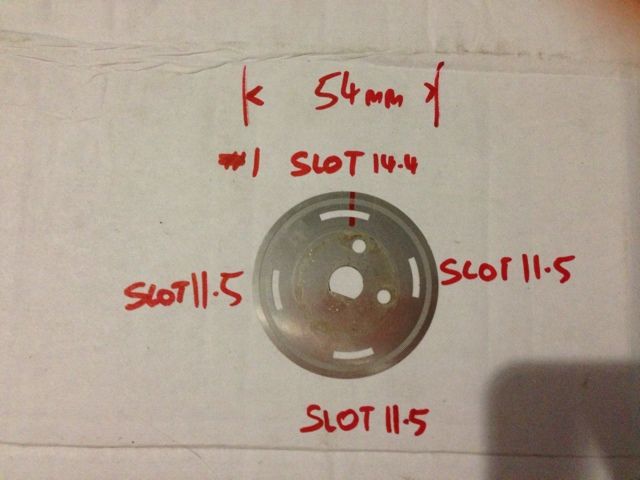
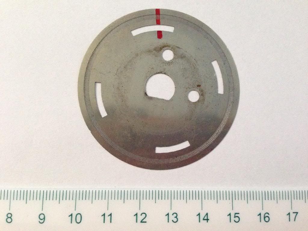
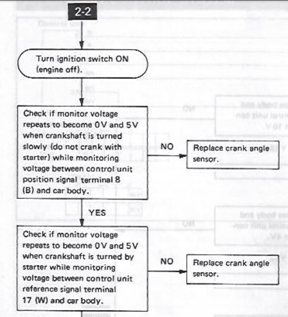
From what I understand The MS3 needs a 0-5v input for the VR circuit and according to the Factory Workshop Manual, this is the kind of output the Subaru / Hitachi CAS has, as seen here:

Image

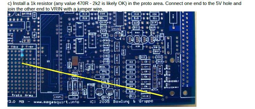
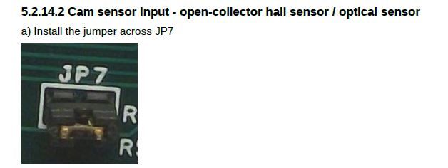
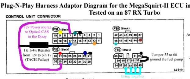
But when I refer back to an old install guide, found here : https://www.diyautotune.com/support/tec ... -rx-turbo/
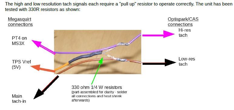
It mentions the install requires a pull-up resistor, which is confusing me.

I really appreciate any help on this, which most likely sounds like a stupid question!
Last edited by Subaru_EA82_4EAT_AWD on Sat Jul 02, 2016 6:58 pm, edited 1 time in total.
Want a neat way to Check & Set Ignition timing AND CRANK the motor at the same time BY YOURSELF?
A little thing I made up... https://youtu.be/PajlPNF5mmQ
slow_hemi6
Super MS/Extra'er
Posts: 4122
Joined: Fri May 07, 2004 3:33 am
Location: Australia

Re: Help understanding Optical CAS pull-up circuits please..

Post by slow_hemi6 »

The service manual shows checking for 5v and 0v from the sensor, but that is with the factory ecu connected. The factory ecu could have 5v pull ups internally. So if you remove the factory ecu you could loose the 5v.
Digital electronics works on States. Usually High, Low and less common the High Z state. Ignoring the high z state, you have high, 5v (3.3v modern), ON and Binary 1 pretty much all being the same thing and 0v, gnd, OFF and binary 0 pretty much all being the same thing. When an input shifts state the micro controller sees that something has happened and can then do something.
Many electronic switches are open collector or in other words ground switching. When they switch they switch to ground. The addition of a pull up resistor will then make that switch point be at the voltage it is pulled up to through the resistor, until the switch closes to ground. At that point it is obviously grounded and at a logic low, the voltage is then dropped across the resistor and the circuit current flowing is being governed by the resistance of the pull up.
Image
Find the Manuals up top under Quick links: Manuals. :RTFM:
Cheers Luke
kjones6039
Super MS/Extra'er
Posts: 1986
Joined: Sat Jul 22, 2006 8:02 pm
Location: Eureka, NV USA
Contact:

Re: Help understanding Optical CAS pull-up circuits please..

Post by kjones6039 »

I hate to be a nit-picker, but when I went to electronics school (albeit, some ~55 years ago), I was taught that electrons flow from negative to positive outside the source!

Certainly not a big deal, but the above picture shows it the other way around.

Ken
1979 Corvette - 383 CID SBC w/ Holley Pro-Jection 900 CFM TBI, 4-85 lb lo-z injectors & Walbro 255 pump
MS2 v3 w/extra 3.4.2 Release
36-1, Delphi LS2/7 coils in wasted spark, driven by v2.0 logic board from JBPerformance
Spartan Lambda Sensor from 14point7
TinyIOX from JBPerformance
Subaru_EA82_4EAT_AWD
Helpful MS/Extra'er
Posts: 122
Joined: Fri Jan 24, 2014 4:52 pm
Location: Australia

Re: Help understanding Optical CAS pull-up circuits please..

Post by Subaru_EA82_4EAT_AWD »

Ah...I hadnt thought of the fact that the factory ECU was still connected, thanks!

That helps a lot!

What I plan on doing is piggybacking the MS3 at first to log the factory cas pattern and try and modify a Nissan decoder to suit the 360 + 4 cam wheel, so that should work fine, then when I go MS3 only I'll fit the pull-up.

I have looked but I cannot find a specific 'how to' for modifying a wheel decoder, can someone point me in the right direction or shall I start a new thread?
Want a neat way to Check & Set Ignition timing AND CRANK the motor at the same time BY YOURSELF?
A little thing I made up... https://youtu.be/PajlPNF5mmQ
billr
Super MS/Extra'er
Posts: 6828
Joined: Sun May 15, 2011 11:41 am
Location: Walnut Creek, Calif. USA

Re: Help understanding Optical CAS pull-up circuits please..

Post by billr »

Well, I don't think you are "nit-picking", Ken. If you are doing electric welding (arc, TIG, MIG, EB) the actual direction of electron flow matters. Also with vacuum tubes, of all kinds, but that is a lost art... And spark-plugs, you can get a debate going about which way polarity is supposed to be, so understanding electron direction flow there must matter too!
racingmini_mtl
Super MS/Extra'er
Posts: 9130
Joined: Sun May 02, 2004 6:51 am
Location: Quebec, Canada
Contact:

Re: Help understanding Optical CAS pull-up circuits please..

Post by racingmini_mtl »

But since the electrons are negatively charged particles, that means their movement indicate a negative current. So for a positive current, showing it going from + to - is the normal and correct way to go. The actual particles moving are going the other way but that's irrelevant for many applications such at the ones involving wiring.

Jean
jbperf.com Main site . . . . . . . . . . . . . . . . . . . . . . jbperf.com Forum
Image
billr
Super MS/Extra'er
Posts: 6828
Joined: Sun May 15, 2011 11:41 am
Location: Walnut Creek, Calif. USA

Re: Help understanding Optical CAS pull-up circuits please..

Post by billr »

The diagram posted is labelled "flow of electrons", not "flow of current". Yes, it does come down somewhat to semantics, but I still insist that there are some electrical disciplines where knowing the difference between electron flow and (conventional) current flow does matter. The diagram is labelled incorrectly; I (and maybe Ken) just didn't want anybody with a tenuous grasp on the subject to get confused by the diagram.
racingmini_mtl
Super MS/Extra'er
Posts: 9130
Joined: Sun May 02, 2004 6:51 am
Location: Quebec, Canada
Contact:

Re: Help understanding Optical CAS pull-up circuits please..

Post by racingmini_mtl »

I'm sorry, I hadn't checked the diagram carefully and only went by the discussion. That label is obviously wrong and that is not nit-picking.

Jean
jbperf.com Main site . . . . . . . . . . . . . . . . . . . . . . jbperf.com Forum
Image
slow_hemi6
Super MS/Extra'er
Posts: 4122
Joined: Fri May 07, 2004 3:33 am
Location: Australia

Re: Help understanding Optical CAS pull-up circuits please..

Post by slow_hemi6 »

It was the best conceptual diagram I could rip from google images at the time. :lol:
I totally agree and I would also describe the arrow as showing conventional current rather than electron flow.
Find the Manuals up top under Quick links: Manuals. :RTFM:
Cheers Luke
kjones6039
Super MS/Extra'er
Posts: 1986
Joined: Sat Jul 22, 2006 8:02 pm
Location: Eureka, NV USA
Contact:

Re: Help understanding Optical CAS pull-up circuits please..

Post by kjones6039 »

Under any circumstances, I am hesitant to argue with guys like Luke, who live down under! You see, I have a theory...........

Since they spend their lives up side down, the blood all flows to their brains, therefore rendering them smarter than we in the northern hemisphere.

Just a theory of course.

Ken

:lol: :lol:
1979 Corvette - 383 CID SBC w/ Holley Pro-Jection 900 CFM TBI, 4-85 lb lo-z injectors & Walbro 255 pump
MS2 v3 w/extra 3.4.2 Release
36-1, Delphi LS2/7 coils in wasted spark, driven by v2.0 logic board from JBPerformance
Spartan Lambda Sensor from 14point7
TinyIOX from JBPerformance
Subaru_EA82_4EAT_AWD
Helpful MS/Extra'er
Posts: 122
Joined: Fri Jan 24, 2014 4:52 pm
Location: Australia

Re: Help understanding Optical CAS pull-up circuits please..

Post by Subaru_EA82_4EAT_AWD »

Thanks for the input about the pullups, and the wisdom about us 'upside-downers'

Can anyone give me an idea of whats involved to modify or write a 360/4 decoder?
Want a neat way to Check & Set Ignition timing AND CRANK the motor at the same time BY YOURSELF?
A little thing I made up... https://youtu.be/PajlPNF5mmQ
jsmcortina
Site Admin
Posts: 39619
Joined: Mon May 03, 2004 1:34 am
Location: Birmingham, UK
Contact:

Re: Help understanding Optical CAS pull-up circuits please..

Post by jsmcortina »

Subaru_EA82_4EAT_AWD wrote:Can anyone give me an idea of whats involved to modify or write a 360/4 decoder?
Not an easy task at all. I'm the only person that has written any CAS decoders for MS3 to my knowledge.

Do you have a photo of the trigger disc?

James
I can repair or upgrade Megasquirts in UK. http://www.jamesmurrayengineering.co.uk

My Success story: http://www.msextra.com/forums/viewtopic ... 04&t=34277
MSEXTRA documentation at: http://www.msextra.com/doc/index.html
New users, please read the "Forum Help Page".
Subaru_EA82_4EAT_AWD
Helpful MS/Extra'er
Posts: 122
Joined: Fri Jan 24, 2014 4:52 pm
Location: Australia

Re: Help understanding Optical CAS pull-up circuits please..

Post by Subaru_EA82_4EAT_AWD »

This is the particular wheel in question, numbers referring to inner slots are approx. straightline lengths in mm, red line is where pickup is on #1 dtc:
Image

Image
Want a neat way to Check & Set Ignition timing AND CRANK the motor at the same time BY YOURSELF?
A little thing I made up... https://youtu.be/PajlPNF5mmQ
billr
Super MS/Extra'er
Posts: 6828
Joined: Sun May 15, 2011 11:41 am
Location: Walnut Creek, Calif. USA

Re: Help understanding Optical CAS pull-up circuits please..

Post by billr »

This is a wheel with optical sensors? Why not make life easy, just fill in holes on both tracks with JBWeld or similar. Make that outer track 36-1 or 36-2 and you can get it running almost instantly.
Subaru_EA82_4EAT_AWD
Helpful MS/Extra'er
Posts: 122
Joined: Fri Jan 24, 2014 4:52 pm
Location: Australia

Re: Help understanding Optical CAS pull-up circuits please..

Post by Subaru_EA82_4EAT_AWD »

Anyway, I'm most likely going to get it running in Basic Trigger mode at first, then I'll take a log and post it up, that will most likely help aye?

Going over the hardware manual today getting ready to pull the trigger on the installation and now I have some more questions about the Pull-up resistors:

For the Low res 'tach' input it says to fit an internal pull-up to the v3.0 board:
Image

For the Hi res 'cam' input it says to fit JP7 which is apparently a pull-up:
Image

And in the Nissan CAS section in the back index it says an external pullup needs to be fitted:
Image

This seems like a paradox and now I'm super confused!
Wouldn't it be better to fit the correct pull-up in EITHER the loom OR the ECU, not both?
Want a neat way to Check & Set Ignition timing AND CRANK the motor at the same time BY YOURSELF?
A little thing I made up... https://youtu.be/PajlPNF5mmQ
jsmcortina
Site Admin
Posts: 39619
Joined: Mon May 03, 2004 1:34 am
Location: Birmingham, UK
Contact:

Re: Help understanding Optical CAS pull-up circuits please..

Post by jsmcortina »

Please re-read the SR20 section. It says to make those loom mods and then follow section 5.2.4. It says nothing about installing a pullup internally or adding JP7 on the MS3X card.

James
I can repair or upgrade Megasquirts in UK. http://www.jamesmurrayengineering.co.uk

My Success story: http://www.msextra.com/forums/viewtopic ... 04&t=34277
MSEXTRA documentation at: http://www.msextra.com/doc/index.html
New users, please read the "Forum Help Page".
Subaru_EA82_4EAT_AWD
Helpful MS/Extra'er
Posts: 122
Joined: Fri Jan 24, 2014 4:52 pm
Location: Australia

Re: Help understanding Optical CAS pull-up circuits please..

Post by Subaru_EA82_4EAT_AWD »

jsmcortina wrote:Please re-read the SR20 section. It says to make those loom mods and then follow section 5.2.4. It says nothing about installing a pullup internally or adding JP7 on the MS3X card.

James
Ah, yep...Thanks, so in effect adding a pull-up to the loom makes the CAS one with a 'built in pull-up' - makes sense.

In the cam section, 5.2.14.2 it says to fit the jumper for optical CAS, but I'm guessing that is only if the CAS doesn't have a 'built in pull-up' then?

So, my next question, is adding a 330ohm resistor from 5v to each signal lead for a pull-up the same as adding a 1kohm resistor from 12v to each signal lead? as per here:
Image

thanks for the help! BTW, what do you think about the wheel pattern?
Want a neat way to Check & Set Ignition timing AND CRANK the motor at the same time BY YOURSELF?
A little thing I made up... https://youtu.be/PajlPNF5mmQ
jsmcortina
Site Admin
Posts: 39619
Joined: Mon May 03, 2004 1:34 am
Location: Birmingham, UK
Contact:

Re: Help understanding Optical CAS pull-up circuits please..

Post by jsmcortina »

Subaru_EA82_4EAT_AWD wrote:In the cam section, 5.2.14.2 it says to fit the jumper for optical CAS, but I'm guessing that is only if the CAS doesn't have a 'built in pull-up' then?
The "Nissan CAS" doesn't use the normal cam input.
So, my next question, is adding a 330ohm resistor from 5v to each signal lead for a pull-up the same as adding a 1kohm resistor from 12v to each signal lead? as per here:
Unsure. I've tested as per the instructions only.
thanks for the help! BTW, what do you think about the wheel pattern?
What ignition/coils does this engine have as standard? One? Wasted spark? Coil-on-plug?

James
I can repair or upgrade Megasquirts in UK. http://www.jamesmurrayengineering.co.uk

My Success story: http://www.msextra.com/forums/viewtopic ... 04&t=34277
MSEXTRA documentation at: http://www.msextra.com/doc/index.html
New users, please read the "Forum Help Page".
Subaru_EA82_4EAT_AWD
Helpful MS/Extra'er
Posts: 122
Joined: Fri Jan 24, 2014 4:52 pm
Location: Australia

Re: Help understanding Optical CAS pull-up circuits please..

Post by Subaru_EA82_4EAT_AWD »

jsmcortina wrote: The "Nissan CAS" doesn't use the normal cam input.
So, JP7 doesn't have anything to do with PT4?
EDIT - I'm feeling rather foolish as I have now done some further reading and found that normal cam input (which I'm guessing JP7 modifies) is pin 32, but PT4 is pin 31 so the external pull up makes sense to me now.
Unsure. I've tested as per the instructions only.
...I'll set it up like that then.
What ignition/coils does this engine have as standard? One? Wasted spark? Coil-on-plug?
Single Coil with Dizzy Cap.
Want a neat way to Check & Set Ignition timing AND CRANK the motor at the same time BY YOURSELF?
A little thing I made up... https://youtu.be/PajlPNF5mmQ
jsmcortina
Site Admin
Posts: 39619
Joined: Mon May 03, 2004 1:34 am
Location: Birmingham, UK
Contact:

Re: Help understanding Optical CAS pull-up circuits please..

Post by jsmcortina »

Basic Trigger using the low-res slots only will be fine for a single-coil. However, you can't run sequential fuel that way.

James
I can repair or upgrade Megasquirts in UK. http://www.jamesmurrayengineering.co.uk

My Success story: http://www.msextra.com/forums/viewtopic ... 04&t=34277
MSEXTRA documentation at: http://www.msextra.com/doc/index.html
New users, please read the "Forum Help Page".
Post Reply