Hey guys I'm working on wiring up my Mega squirt to my RB20.
I have mostly everything done except I am a little confused on the wiring for the CAM angle sensor.
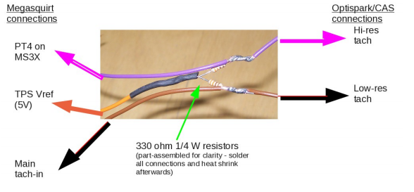
In the manual it says to use the 5v cable for the TPS and wire resistors to the high and low signal for the Cam as seen in the image below from the manual.
My question that the image doesn't clearly illustrate.
Shouldn't the 5V reference cable still go to the TPS to power it?
This image almost states that opposite. IF so where would I pull my 5v for the TPS from?
It would be tied to the TPS VREF wire in addition to the TPS being connected.
I'm also not sure how well a 5V signal will work for the RB20 CAS. The last one I did (which was connected to a different ECM FWIW) was connected to 12V for the power source. There were also no external pullup resistors needed either. If this 5V is ONLY for the pull up then the 5V is what you'd want.
You could add these pull up resistors to the MS internally for a cleaner and probably more reliable installation.
Tha Toy: 1973 Datsun 240Z Turbocharged, and loads of fun, now MS'd Tha Otha Toy: 1923 T-bucket Hot Rod, Currently Sniper'd Tha Daily: 2005 Chevy Blazer Tha Summer Daily: 1987 Buick Skyhawk hatchback Tha Long Term Project: 1985 GMC S-10 Jimmy, hasn't been fun for a while
Six Shooter, Thank you so much for the input. The CAS will have it's own 12V power supply going directly to power. The 5V would simply be for pull up only.
I was figuring it would go to the TPS as well just wanted to be sure. I'm going to go ahead and do it externally since I did not build the Megasquirt and bought a pre-assembled one.
I'll give it all a try and go from there.
Alrighty, So I have finished my wiring for the RB20 and got the motor all setup and installed into the car.
I have confirmed everything is working except when I turn the motor over I am getting no RPM signal.
I have confirmed that I have my wiring correct for the pin out on the CAS and each signal output from the CAS is getting the 5V pullup.
I have tested my CAS and confirmed that it is working as it should along with confirming that I am getting a signal back to the ECU both on the Crank input on the MS3 board and on the PT4 input on the MS3X board.
Changing the Ignition input capture to Rising Edge or Falling Edge makes no difference and I do have the CAM input set to MS3X cam input.
The only thing I am confused on as what might be the possibility, whenever the ECU is going to the MS3X Cam input for the input there's nothing there since it's going to the PT4 wire.
Is there something I am supposed to change to tell TS to grab the cam input from the PT4 wire?
The ECU I am using is a pre-built MS3 V3.57 which I then added the MS3X board.
I did notice that the main page did state to build the ECU to trigger for inverted VR output.
*EDIT* I did just find the jumpers for JP1 and J1 to setup the ECu for inverted VR output. I will give this a try tomorrow.
Another detail to add. I have also reset the POTS near the Jumpers and on the MS3X board as well.
Just out of curiosity to anyone who can answer. Why do we send the High signal to the PT4 wire? There is no where in TS to find the Cam signal at the PT4 wire unless it is automatically programmed to do that on the back end.
Would PT5 be the better wire to send the signal to since I am able to directly tell TS to grab the signal there?
RGNHD wrote:Another detail to add. I have also reset the POTS near the Jumpers and on the MS3X board as well.
Just out of curiosity to anyone who can answer. Why do we send the High signal to the PT4 wire? There is no where in TS to find the Cam signal at the PT4 wire unless it is automatically programmed to do that on the back end.
Would PT5 be the better wire to send the signal to since I am able to directly tell TS to grab the signal there?
The high res signal is actually the crank signal, not the cam signal.
The reason it goes to PT4 is because the main tach input for the crank isn't fast enough to read the signal.
jsmcortina wrote:PT4 is automatically used. The MS3X cam input can't cope with the high frequency of the "hi-res" signal from the CAS.
James
Thanks for clearing that up guys. So as long as in TS the cam setting is set to MS3X Cam in, It should automatically pull from the PT4 cable?
Is there also anyway for me to confirm that this is what's happening with MegaViewer?
Just tried changing the inner and outer signal on the CAS.
No change what so ever. Here's the log file from today.
I also went through the harness and double checked Continuity.
I plugged only the CAS in and attempting to crank the car. Still no RPM.
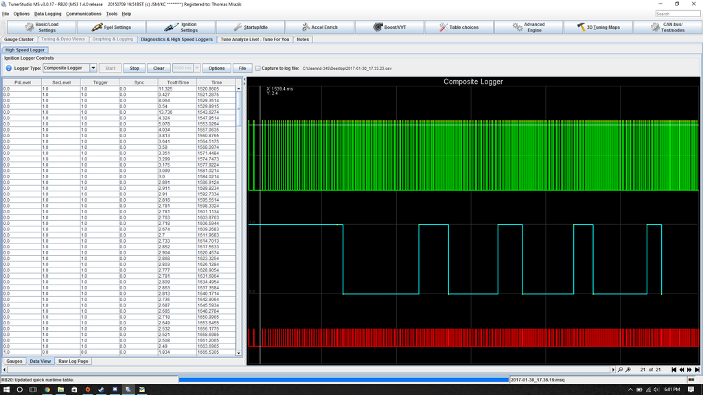
I ran the Diagnostics logger while cranking and this is what I see. Again with only the CAS plugged in.
Can anyone tell exactly what it's reading or if this is a good or bad thing?
jsmcortina wrote:From the image that looks about right, although the red line shows you aren't synced.
James
James, Thank you for the explanation. So if I understand the log correctly, the green should be the high signal from the CAS and the blue the low.
What would be the cause of it not being synced? My POTS settings on the boards?
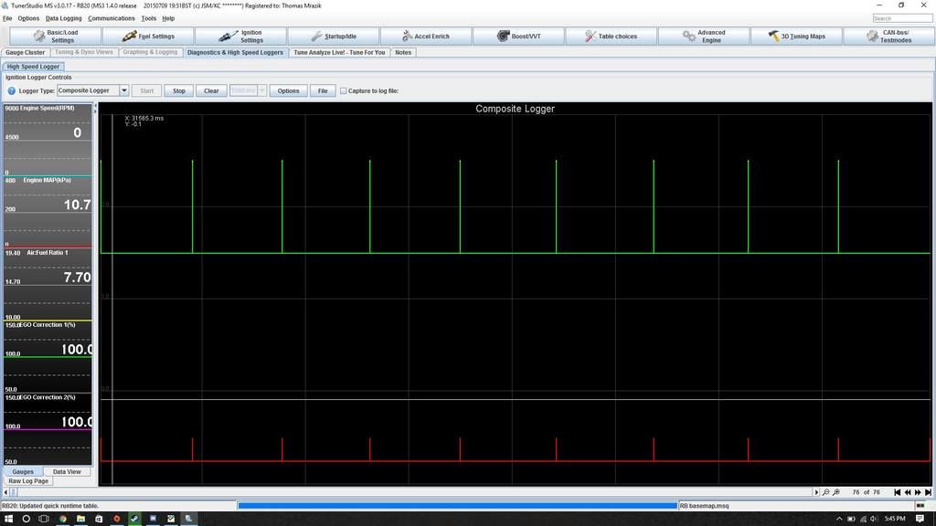
So after Ohming everything for continuity and messing with the pots on both boards my composite logger began to look like this.
Obviously I am not longer getting a crank signal. The cam signal looks much better but no crank signal.
I realized at this point my CAM plug is deteriorating and the clip to hold pressure on the crank pin has completely broken off.
At this point I ordered a new plug to eliminate that being the cause of all my headaches.
Once the plug comes in hopefully this will resolve everything.
I'm not sure why you think that cam signal "looks better" ? There are 360 teeth per cam rev, so the previous images looked ok.
Set the mainboard pots as per the manual and do the 2.5V check. The MS3X pots aren't relevant with the Nissan CASes. I've bench tested SR20 and RB25 CASes to test ECUs I supplied to customers and they worked ok.
I checked the first CSV file you posted, the "crank" and "cam" inputs are swapped for sure. Please set the pots as per the manual and take a new log.
Is the RB20 CAS the same as the RB25 ?
jsmcortina wrote:I checked the first CSV file you posted, the "crank" and "cam" inputs are swapped for sure. Please set the pots as per the manual and take a new log.
Is the RB20 CAS the same as the RB25 ?
James
Out of curiosity how did you confirm that the inputs were swapped? Just so I know how to check for that in the future myself.
I'm currently awaiting the new plug as it has seriously degraded after taking it on and off so many time throughout my testing. I'll make sure to update you guys after I get the new one wired in. Hoping it should be here at the beginning of next week.
The green line is the "cam" input and should be a lot of tiny spikes packed closely together on an RB motor. The blue line represents "crank" and should be a much slower square wave signal.
Matt Cramer -1966 Dodge Dart slant six running on MS3X