Fuel Level Sensor

General support questions and announcements for MS3. See also MS3 manuals.

Moderators: jsmcortina, muythaibxr

Post Reply
Raymond_B
Super MS/Extra'er
Posts: 1399
Joined: Thu Mar 06, 2014 2:17 pm
Location: Texas
Contact:

Fuel Level Sensor

Post by Raymond_B »

OK, did some searching and it appears that in order to run a fuel level gauge I need to craft a circuit using the original tank sender and a 5v pullup resistor. Is the below circuit correct? Also which ground? The MS sensor ground or chassis? I would think MS sensor if I use the MS 5v vRef as source voltage?

Image

Also here is the fuel level sensor specs.

Empty Stop 15 Ohms (Below E)
Empty 22.5 Ohms
Full 145 Ohms
Full Stop 160 Ohms (Above F)
1995 Ford Lightning. Dart based 427 Windsor, Novi 2000, full sequential, E-85, etc. MS3X/v3.57
http://www.buildpics.org/
billr
Super MS/Extra'er
Posts: 6828
Joined: Sun May 15, 2011 11:41 am
Location: Walnut Creek, Calif. USA

Re: Fuel Level Sensor

Post by billr »

Yes, that should work. You just need to calibrate that sensor input in TS. Yes, run the ground back to an MS ground for best results, but it would probably be good enough for a fuel gauge just using chassis ground; unless you are fond of running the tank down to the bitter end...
racingmini_mtl
Super MS/Extra'er
Posts: 9130
Joined: Sun May 02, 2004 6:51 am
Location: Quebec, Canada
Contact:

Re: Fuel Level Sensor

Post by racingmini_mtl »

As mentioned, this should work and you should use a sensor return ground. Note however that you will get a rather coarse resolution because you will be using from about 10% (empty-to-full) to about 12% (stop-to-stop) of the full possible range of the input. But for a fuel gauge that should be good enough.

Jean
jbperf.com Main site . . . . . . . . . . . . . . . . . . . . . . jbperf.com Forum
Image
Raymond_B
Super MS/Extra'er
Posts: 1399
Joined: Thu Mar 06, 2014 2:17 pm
Location: Texas
Contact:

Re: Fuel Level Sensor

Post by Raymond_B »

racingmini_mtl wrote:As mentioned, this should work and you should use a sensor return ground. Note however that you will get a rather coarse resolution because you will be using from about 10% (empty-to-full) to about 12% (stop-to-stop) of the full possible range of the input. But for a fuel gauge that should be good enough.

Jean
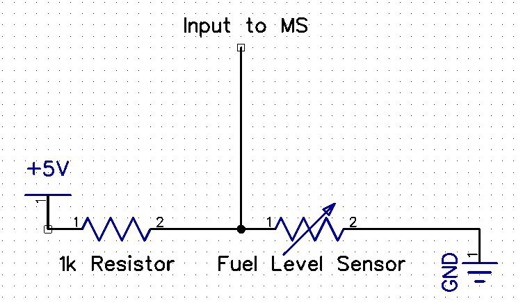
Is there another way to get a higher resolution?
1995 Ford Lightning. Dart based 427 Windsor, Novi 2000, full sequential, E-85, etc. MS3X/v3.57
http://www.buildpics.org/
krisr
Master MS/Extra'er
Posts: 799
Joined: Wed Aug 17, 2005 1:17 am
Location: Sydney, Australia

Re: Fuel Level Sensor

Post by krisr »

I'm running fuel level into an ADC on my IOX, which in-turn drives my fuel gauge in the dash. I calibrated everything in the ECU and it works great. It is quite jumpy as fuel sloshes around even with the lag factor set as low as possible (10, I think?). If we could get a "Fuel Level" mode or if the lag factor could be time based, it'd be great for the MS to sample the fuel level sender every minute and just perform an average of the last few readings so it adjusts at a more sane rate.
Sydney, Australia
1971 Holden Monaro HQ
MS3X Sequentially fuelled 400 Pontiac
Raymond_B
Super MS/Extra'er
Posts: 1399
Joined: Thu Mar 06, 2014 2:17 pm
Location: Texas
Contact:

Re: Fuel Level Sensor

Post by Raymond_B »

Thank you. I imagine the jumpiness is due to the resolution being so low, but I can live with that :)

I am curious though, I plan on using a Microsquirt with the I/O-Box firmware. What is the difference between a coolant temp sensor and a fuel level sensor? Both of them just provide a varying ground connection do they not? Why couldn't I use the coolant or IAT pin of the Microsquirt and do away with the whole voltage divider circuit?
1995 Ford Lightning. Dart based 427 Windsor, Novi 2000, full sequential, E-85, etc. MS3X/v3.57
http://www.buildpics.org/
billr
Super MS/Extra'er
Posts: 6828
Joined: Sun May 15, 2011 11:41 am
Location: Walnut Creek, Calif. USA

Re: Fuel Level Sensor

Post by billr »

Coolant sensors typically range from 100K to 200 ohms, with that series resistor being 2490 ohms. For similar resolution, your 22.5 to 145 ohm fuel sensor would need a series resistor much lower than the 1K you intend. This would probably put too much load (current draw) on the 5V ref supply. You could use a different supply for that 5V feed to the fuel sensor, but accuracy would be compromised because the ADC reading the resultant signal would not be referenced to that "different" 5V supply.

Note that temp sensors, like the CLT or MAT are assumed to be reverse-acting, a higher value to be read (temp or fuel level) results in a lower input voltage to MS. This wouldn't be a problem using one of the generic sensor inputs for your fuel gauge, but I thought I should toss that out to keep you informed... or confused.
Raymond_B
Super MS/Extra'er
Posts: 1399
Joined: Thu Mar 06, 2014 2:17 pm
Location: Texas
Contact:

Re: Fuel Level Sensor

Post by Raymond_B »

billr wrote:Coolant sensors typically range from 100K to 200 ohms, with that series resistor being 2490 ohms. For similar resolution, your 22.5 to 145 ohm fuel sensor would need a series resistor much lower than the 1K you intend. This would probably put too much load (current draw) on the 5V ref supply. You could use a different supply for that 5V feed to the fuel sensor, but accuracy would be compromised because the ADC reading the resultant signal would not be referenced to that "different" 5V supply.

Note that temp sensors, like the CLT or MAT are assumed to be reverse-acting, a higher value to be read (temp or fuel level) results in a lower input voltage to MS. This wouldn't be a problem using one of the generic sensor inputs for your fuel gauge, but I thought I should toss that out to keep you informed... or confused.
Thanks Bill, actually my question is why do we even need the 5v circuitry if we were to use a pin already setup to read a thermistor?
1995 Ford Lightning. Dart based 427 Windsor, Novi 2000, full sequential, E-85, etc. MS3X/v3.57
http://www.buildpics.org/
billr
Super MS/Extra'er
Posts: 6828
Joined: Sun May 15, 2011 11:41 am
Location: Walnut Creek, Calif. USA

Re: Fuel Level Sensor

Post by billr »

If you use one of the existing "thermistor readers" you wouldn't be able to calibrate the gauge, and it would read "backwards"; and you would be restricted to running off the 5V ref, so the limits on how low the series resistor (1K in your example) could go to improve gauge resolution would be in effect. You probably already understood that, but I wanted to be sure...
jacky4566
Helpful MS/Extra'er
Posts: 112
Joined: Mon Aug 31, 2015 10:05 am

Re: Fuel Level Sensor

Post by jacky4566 »

I posted on your facebook post but ill put it here too.

If you want more resolution you need a lower pull up resistor closer to the target. However the problem with that is the lower your resistance the more current will flow overall which will lead to overheating and/or overloading the 5v regulator.

As stated, the problem is your fuel sender has a very low resistance. It was made to drive a mechanical pointer on a dash not feed into a micro controller.

If you play with this voltage divider calc you will see what i mean.
http://www.ohmslawcalculator.com/voltag ... calculator

I would start with 500ohm pull up since that will give you plenty of range and is still only pull 0.01 Amps on the 5v line.
The output range will be 1.124v to 0.215v. The ADC value will range between 230 to 44. Plenty of range.

You could also use the 12v as a source for more range but this is risky since
A. more chances to over volt the ECU
B. 12v is unreliable and fluctuates between 10-16vdc
C. now your flowing 0.288 Watts through the resistor.

Modern cars use either high resistance floats or Capacitance senders like this:
http://www.speedhut.com/ecommerce/produ ... ender-(3-5

Overall its not a big deal, just requires some extra conditioning.
Raymond_B
Super MS/Extra'er
Posts: 1399
Joined: Thu Mar 06, 2014 2:17 pm
Location: Texas
Contact:

Re: Fuel Level Sensor

Post by Raymond_B »

Thank you for the extra explanation! I meant to change my original drawing to reflect the new resistor value. I plan on using 510 ohm as I have a bunch on hand.

Image
1995 Ford Lightning. Dart based 427 Windsor, Novi 2000, full sequential, E-85, etc. MS3X/v3.57
http://www.buildpics.org/
Karathos
MS/Extra Newbie
Posts: 14
Joined: Sat Feb 06, 2016 6:36 am

Re: Fuel Level Sensor

Post by Karathos »

Looking for a little info here Facebook told me to post here,

I want to set up My fuel gauge on my raspberry pi dash. How do I get my MS2 V3 to read my sending unit?

On my car full is 1-5 ohm
Empty is 103-117 ohm.

I’m taking it will need some type of pull-up. But I’m pretty lost on how to build this

I followed the above information the best I could.
I attempted to set this up using ADC. I jumpered from Spare3 to JS4. With a 580 Ohm resister in the jumper.

I might be confused on how the ADC from the JS4 works orI might be missing some kind of crucial step.

Does the JS4 supply 5vref? Or do I need to supply the circuit with 5V?

Also once in tunerstudio, I just create a gauge listed as ADC7?
neneossa
MS/Extra Newbie
Posts: 34
Joined: Sat Aug 29, 2015 2:39 pm

Re: Fuel Level Sensor

Post by neneossa »

Raymond_B wrote:Thank you for the extra explanation! I meant to change my original drawing to reflect the new resistor value. I plan on using 510 ohm as I have a bunch on hand.

Image
hi, did it work?
Post Reply