MS3X is now built and passed the relevant tests in the build process - now time to do the setup.
I assume I just follow the doc MS3 Setup 1.4.
Q. 1. As I will be doing the setup at a desk I assume I can use my Jim Stim to power the ECU and provide sensor input etc during setup. Or at this stage do I need to provide separate 12v power as the setup document says.
Q. 2. Downloaded and installed Java, Tuner studio and Megalog viewer. Downloaded firmware MS3 1.5.0 but not yet installed. Went to the FTDI site to download the USB/Serial controller driver but not sure what I need to actually download as there are a few different items. Took a punt and downloaded the VCP drivers but I cannot find anywhere to execute and install the zipped files. The MS3 Setup document says to run the "setup executable" file but I cannot find any such file. So any advice on how to install these drivers would be appreciated. So until I get the USB working I cannot upload the Firmware to the ECU.
I downloaded and installed the Port Check and it does not show any ports but the computer does know the ECU is connected to it but it is not recognized and says it has no drivers.
Q. 3. Where do I get an initial engine map (Edis 8 for ignition and batch injection) to load into the ECU?
No doubt one I get the firmware loaded and move forward I guess I will have more question - I appreciate your patience.
Thanks
Garry
MS3X - Am I on the right track?
Moderators: jsmcortina, muythaibxr
-
MegaMicra
- Helpful MS/Extra'er
- Posts: 142
- Joined: Tue Feb 14, 2017 2:23 pm
- Location: Manchester, England
Re: MS3X - Am I on the right track?
I found unzipping the file shows the executable driver file. You just double click it to install it. Then plug in the Megasquirt and Windows did the rest.
Edit: On the ftdi page where you choose the driver file to download, i went to the far right of the table and chose 'setup executable'. That is the zipped one that's got the .exe file in.
Sent from my Nexus 5X using Tapatalk
Edit: On the ftdi page where you choose the driver file to download, i went to the far right of the table and chose 'setup executable'. That is the zipped one that's got the .exe file in.
Sent from my Nexus 5X using Tapatalk
Last edited by MegaMicra on Wed Sep 06, 2017 5:12 am, edited 1 time in total.
-
MegaMicra
- Helpful MS/Extra'er
- Posts: 142
- Joined: Tue Feb 14, 2017 2:23 pm
- Location: Manchester, England
Re: MS3X - Am I on the right track?
As for an initial map, the MS3 doesn't require one. If someone has already got one you can use then all the better, but if you set it up in TunerStudio as per the manual with all your relevant settings and such the engine should start.
Sent from my Nexus 5X using Tapatalk
Sent from my Nexus 5X using Tapatalk
-
garrycol
- Helpful MS/Extra'er
- Posts: 130
- Joined: Tue Sep 10, 2013 4:49 pm
- Location: Canberra, Australia
Re: MS3X - Am I on the right track?
Thanks for that response - fixed my USB/Serial driver problem - I had downloaded the correct zip file but didn't appreciate the 'executable file" was separate - as you indicated I downloaded the file to the right of the page (I had missed that) and now all seems to be good - port recognised and firmware is in the process of being uploaded to the MS3 CPU right now.
The last part of the Command Prompt process of uploading the firmware to the ECU has switch off MS3 - remove Jumper and then restart MS3 - but I did not have the jumper on - is that an issue?
I appreciate your response and I will continue tomorrow following the steps in the setup document.
Garry
The last part of the Command Prompt process of uploading the firmware to the ECU has switch off MS3 - remove Jumper and then restart MS3 - but I did not have the jumper on - is that an issue?
I appreciate your response and I will continue tomorrow following the steps in the setup document.
Garry
Re: MS3X - Am I on the right track?
IMHO, it's better to start with the default MS map than to use one said to be suitable for your engine - unless buying a full Plug and Play system. As with modified engines (like fitting an MS) no two are usually the same. So many options like type of ignition and so on.
Once you have it running reasonably well - which should be easy enough - by all means compare the VE tables etc from another's tune from a similar engine.
Once you have it running reasonably well - which should be easy enough - by all means compare the VE tables etc from another's tune from a similar engine.
Rover SD1 3.5 EFI
MS2 V3
EDIS
Tech Edge O2
London UK.
MS2 V3
EDIS
Tech Edge O2
London UK.
-
MegaMicra
- Helpful MS/Extra'er
- Posts: 142
- Joined: Tue Feb 14, 2017 2:23 pm
- Location: Manchester, England
Re: MS3X - Am I on the right track?
You only need that jumper if you have any issues with firmware not loading. I never had mine on either on the first upload.
Sent from my Nexus 5X using Tapatalk
Sent from my Nexus 5X using Tapatalk
-
garrycol
- Helpful MS/Extra'er
- Posts: 130
- Joined: Tue Sep 10, 2013 4:49 pm
- Location: Canberra, Australia
Re: MS3X - Am I on the right track?
Thanks for the information on the jumper - seems to have worked all OK.
Dave - thanks for your comments - yes I was just looking for a map to get the engine basically running - I appreciate every engine configuration is unique and that the map will be refined as tuning progresses. I assume the basic tune in Tuner Studio will have the flexibility to allow for different engines to get it going OK.
I have been reading up on the "self learning -tuning" function - Plug and Play - but I see it is really basic and just provides a basis for further tuning. It would be nice if it was like many of the propriety EFI systems that are totally plug and play with no extra tuning is required - unless you wanted to. In my circumstance that would work really well.
Thanks to every one - as always great information and a help.
No doubt as I work through the setup instructions and Tuner Studio etc I have have more questions.
Garry
-
garrycol
- Helpful MS/Extra'er
- Posts: 130
- Joined: Tue Sep 10, 2013 4:49 pm
- Location: Canberra, Australia
Testing MS3X - JimStim
I am working through the Setup manual and Tuner Studio. Seems basically OK but as the hardware on the engine is not yet complete, I am wanting to setup the MS3X to ensure that my soldering is all OK and that I have the right jumpers on etc.
So wanting to do the setup on my kitchen table - using JimStim so that I know all is OK and when I do the setup for real in the truck and something does not work I will know it is hardware or wiring on the engine rather than a problem with the ECU.
Now the setup manual assumes you are connecting to actual sensors like the TPS which I will not be doing - so for this example I want to use JimStim.
On this - as I have MS3X should I have got the extra JimStimX card - my reading seems to indicate yes.
I have looked through the documentation and googled it but I cannot seem to find any single document on how to setup and test ECU functionality using JimStim - is there such a document or do I just follow the Setup manual and use JimStim functions to mimic sensors instead of using the real items?
As I said once all the hardware and wiring on the engine is complete and I have mounted the ECU I will go back over the Setup process using the real sensors mounted on the engine.
Thanks
Garry
-
garrycol
- Helpful MS/Extra'er
- Posts: 130
- Joined: Tue Sep 10, 2013 4:49 pm
- Location: Canberra, Australia
Re: MS3X - Am I on the right track?
Ok I will get the JimStimX extension card and then just follow the MS3X Setup documents using the JimStim for sensor input.
-
SwedCharger-67
- Experienced MS/Extra'er
- Posts: 265
- Joined: Sun Dec 23, 2012 2:20 pm
- Location: Nordmaling, Sweden
Re: MS3X - Am I on the right track?
You are on the right track, and I think you are doing a good job!
I'm sure you will find the JimStim boards very useful...I did. Very easy to spot some strange/unsuitable settings in the MS3X. My E85 fueled engine started right away with the default fuel map that was generated once all parameters were programmed.
I'm sure you will find the JimStim boards very useful...I did. Very easy to spot some strange/unsuitable settings in the MS3X. My E85 fueled engine started right away with the default fuel map that was generated once all parameters were programmed.
Martin, Sweden
Mopar 512 cui, 8.4 liters, high compression, fuel E85, full sequential control by MS3X, burning rubber just blipping the throttle...
Mopar 512 cui, 8.4 liters, high compression, fuel E85, full sequential control by MS3X, burning rubber just blipping the throttle...
-
garrycol
- Helpful MS/Extra'er
- Posts: 130
- Joined: Tue Sep 10, 2013 4:49 pm
- Location: Canberra, Australia
Re: MS3X - Am I on the right track?
Thanks for the positive comments 
Garry
Garry
-
garrycol
- Helpful MS/Extra'er
- Posts: 130
- Joined: Tue Sep 10, 2013 4:49 pm
- Location: Canberra, Australia
Re: MS3X - Am I on the right track?
Got the JimStimXgarrycol wrote:Ok I will get the JimStimX extension card and then just follow the MS3X Setup documents using the JimStim for sensor input.
In setting up the JimStim I have been following the instructions here http://www.jbperf.com/JimStim/JimStim_v ... .html#mode and built the matching JimStimX with instructions from DIYAutotune.
I have been able to set up the correct wheel mode for a 36-1 trigger wheel with dip switch 3 set up on the Stim. I have connected 5v power from the Stim pin #26 to the StimX pin #5 and jump wired the required O2 pins on the Stim so at the moment I have gauge response on Tunerstudio for O2, CLT and TPS . No Tacho though.
The MS3X and StimX is being 12v powered externally through the Stim, with a USB connection between the MS3X and the computer to allow data connection. No serial connection.
However some of the aspects of the setup are not clear to me.
1. TACH – Signal Inversion.
Do I need the Primary Tach signal to be inverted? Stim Dip Switch #8 up for inverted; down for normal.
Do I need to activate a secondary tach at Dip Switch #7 – what is the secondary tach? Does this need to be inverted?
I have assumed I need a Primary Tach signal only that is not inverted so Dip Switch #8 up and have a jump lead joining the top two Primary Tach pins.
Do I need to activate a secondary tach at Dip Switch #7 – what is the secondary tach? Does this need to be inverted?
The Tach instructions then go on to talk about 5v and 12v pull ups – what is a Pull Up?
Do I need the 5V setting or the 12V setting? (instructions should explain this) No sure about this so I have jumped the 5V Pull Up for Primary Tach only.
With these jumps in place the Tach does not work on Tuner Studio.
2. Ignition and IAC LEDs
Not sure how to connect the 6 LEDs – the instructions say to connect the pin from the 10 pin header to the correct pin on the 19 pin header. As each LED has its own pin on the 10 point header and the 19 pin header has only one pin for IGN Pin #36, which pin on the 10 pin header is supposed to be jumped to IGN Pin #36?
The instructions then go on to talk about connecting the IAC LEDs – but talks about a MS2 daughter board – but I have MS3 – does it matter?
When connecting the relevant pins from the 10 pin header to the A and B pins on the 19 pin header does pin #7 go to 1A on the 19 pin header and pin #8 go to 1B on the 19 pin with #9 to 2A and #10 to 2B. Is this correct?
3. Serial Communication and USB power supply
This section talks about serial communications using a serial cable and using a USB to power the Jim Stim and MS and the instructions for dip switches and jumpers revolve around this.
However I am using a fused external 12v supply to power the Jim Stim which then powers the JimStim X and MS3X – I am not using a serial cable to connect the MS3X to TunerStudio in my computer but using the USB to transfer data – no power supply function.
So for my setup is there any jumper/dipswitch setting I have to make?
4. Spare ADC Signal
The instructions talk about a spare ADC potentiometer on the JimStim board? With a MS3X system what function would this be good for?
Lastly with the JimStim setup do I just follow the instructions on setting up the MS3X ECU but just use JimStim sensor inputs rather than real sensor inputs or are their instructions that I have not found for specifically setting up the ECU using JimStim/X?
Thanks
Garry
-
garrycol
- Helpful MS/Extra'er
- Posts: 130
- Joined: Tue Sep 10, 2013 4:49 pm
- Location: Canberra, Australia
Re: MS3X - Am I on the right track?
Any advice?
-
garrycol
- Helpful MS/Extra'er
- Posts: 130
- Joined: Tue Sep 10, 2013 4:49 pm
- Location: Canberra, Australia
Re: MS3X - Am I on the right track?
Any advice?
-
billr
- Super MS/Extra'er
- Posts: 6828
- Joined: Sun May 15, 2011 11:41 am
- Location: Walnut Creek, Calif. USA
Re: MS3X - Am I on the right track?
I'm not clear what your immediate question/need is. There were a lot of words there, and I kind of got lost. I'll try studying it again, but a short synopsis might get you help sooner.
-
MegaMicra
- Helpful MS/Extra'er
- Posts: 142
- Joined: Tue Feb 14, 2017 2:23 pm
- Location: Manchester, England
Re: MS3X - Am I on the right track?
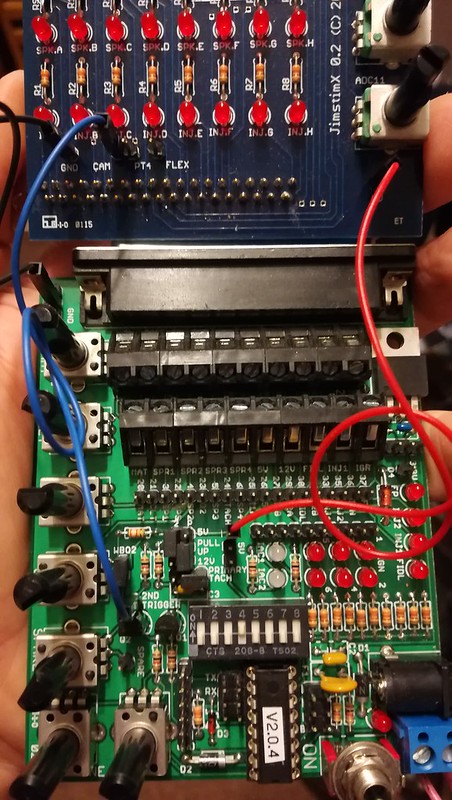
I sent this pic to another member yesterday to help them, but it seems appropriate for your issue also. This is how I set up my Jimstim and JimstimX.
It's set to 60-2 but you can set it to whatever wheel pattern you like as long as you also tell tunerstudio.
It's set as 12v pull up vr for the primary tach and 5v pull up for the secondary cam sensor. Make sure you set the trim pots on the ms3 main board and MS3X board to suit. Hope this helps.
Sent from my WAS-LX1A using Tapatalk
-
billr
- Super MS/Extra'er
- Posts: 6828
- Joined: Sun May 15, 2011 11:41 am
- Location: Walnut Creek, Calif. USA
Re: MS3X - Am I on the right track?
I'll try the easy ones first:
3. Serial Communication and USB power supply
This section talks about serial communications using a serial cable and using a USB to power the Jim Stim and MS and the instructions for dip switches and jumpers revolve around this.
However I am using a fused external 12v supply to power the Jim Stim which then powers the JimStim X and MS3X – I am not using a serial cable to connect the MS3X to TunerStudio in my computer but using the USB to transfer data – no power supply function.
So for my setup is there any jumper/dipswitch setting I have to make? No jumpers or settings are needed to power through the little (blue) 2-pin block; just connect 12V there and you are done.
4. Spare ADC Signal
The instructions talk about a spare ADC potentiometer on the JimStim board? With a MS3X system what function would this be good for? That "spare" pot is simply a handy way to obtain a variable 0-5V signal. Connect it to any input you want to test, and virtually any could be tested to some extent with it. Even an AC input, like VSS or CKP should show some response if the pot is rotated back-and-forth rapidly.
Lastly with the JimStim setup do I just follow the instructions on setting up the MS3X ECU but just use JimStim sensor inputs rather than real sensor inputs or are their instructions that I have not found for specifically setting up the ECU using JimStim/X? Do you mean anything special to do in TS? No, just do the MSQ as needed for the sensors you intend to use. When you fiddle with the pertinent Stim pot you should see a response.
-
garrycol
- Helpful MS/Extra'er
- Posts: 130
- Joined: Tue Sep 10, 2013 4:49 pm
- Location: Canberra, Australia
Re: MS3X - Am I on the right track?
Now you understand my problem - following the setup instructions I got lost - lots of words, not a lot of understanding.billr wrote:I'm not clear what your immediate question/need is. There were a lot of words there, and I kind of got lost. I'll try studying it again, but a short synopsis might get you help sooner.
The synopis is - all relate toJimStim/X:
Tach - do I need a to invert the primary tach?
- do I need a secondary tach and does it need to be inverted (what is a secondary tach)
Pull Ups - what are pull ups?
- do I need a 5v pull up or a 12v pull up?
Ignition LEDs - Which pin on the 10 pin header has to be connected to which pin (Ign Pin?) on the 19 pin header to make the ignition LEDS work?
IAC LEDs - When connecting the relevant pins from the 10 pin header to the A and B pins on the 19 pin header, does pin #7 go to 1A on the 19 pin header and pin #8 go to 1B on the 19 pin with #9 to 2A and #10 to 2B.
Your other post answers my other queries.
I appreciate you taking the effort to give me a hand.
Thanks
Garry
-
garrycol
- Helpful MS/Extra'er
- Posts: 130
- Joined: Tue Sep 10, 2013 4:49 pm
- Location: Canberra, Australia
Re: MS3X - Am I on the right track?
Thanks for the pic and information. I can see it also relates to some of my questions.MegaMicra wrote:I sent this pic to another member yesterday to help them, but it seems appropriate for your issue also. This is how I set up my Jimstim and JimstimX.
It's set to 60-2 but you can set it to whatever wheel pattern you like as long as you also tell tunerstudio.
It's set as 12v pull up vr for the primary tach and 5v pull up for the secondary cam sensor. Make sure you set the trim pots on the ms3 main board and MS3X board to suit. Hope this helps.
So as I am using a VR sensor I should be using the 12v pull up for the primary tach as you have done and use the 5v pull up for the secondary cam sensor - my engine has a cam sensor.
You said - "Make sure you set the trim pots on the ms3 main board and MS3X board to suit". I did ask in another thread about this as it is mentioned in the setup instructions but I could not find how to actually set the trim pots up on the boards. Any pointers on this would be helpful - I kept the cases off the MS3X in anticipation of it being required in the setup but the boards were moving around and I kept on bending the LEDs so have put the circuit boards into their cases to protect the boards etc.
I also thank you for your input - I appreciate it.
Cheers
garry
-
MegaMicra
- Helpful MS/Extra'er
- Posts: 142
- Joined: Tue Feb 14, 2017 2:23 pm
- Location: Manchester, England
Re: MS3X - Am I on the right track?
OK, so if your using a vr sensor for your crank input you NEED a link wire between VRIN & TACHSELECT, and also a link wire between VROUT & TSEL. Then you need to turn both R52 & R56 12 turns anticlockwise. This is just to make sure they're at there initial positions. You can't overturn them.
For your cam sensor input you need to turn R11 & R32 on the MS3X board again all the way anticlockwise, 12 turns will be OK again.
You then need to turn R11 clockwise 3 turns. There is a test point right next to it called ZC TEST POINT. If you want you can check it reads around 2.5volts.
Don't worry about JP7 the pull up jumper, just leave it unjumpered for now.
Sent from my WAS-LX1A using Tapatalk