Question about Crank/Cam VR Sensor Wiring, Shields, and GND

Ask questions about DIY board assembly issues, fault finding and testing. (Covers all Megasquirt versions and board.)

Moderators: jsmcortina, muythaibxr

Post Reply
casey l
MS/Extra Newbie
Posts: 14
Joined: Sun May 31, 2009 12:54 pm

Question about Crank/Cam VR Sensor Wiring, Shields, and GND

Post by casey l »

Hi Everyone,

I am getting back into Megasquirt with a new project. A few years ago I had a very reliable Starion running MS2 Extra, With a 36-1 crank wheel, Ford EDIS VR Sensor, and GM coils running in wasted spark. I am now preparing this ECU & Harness to be ran on a 1999 Subaru Impreza which will run Subaru 6/7 and require a CAM input.

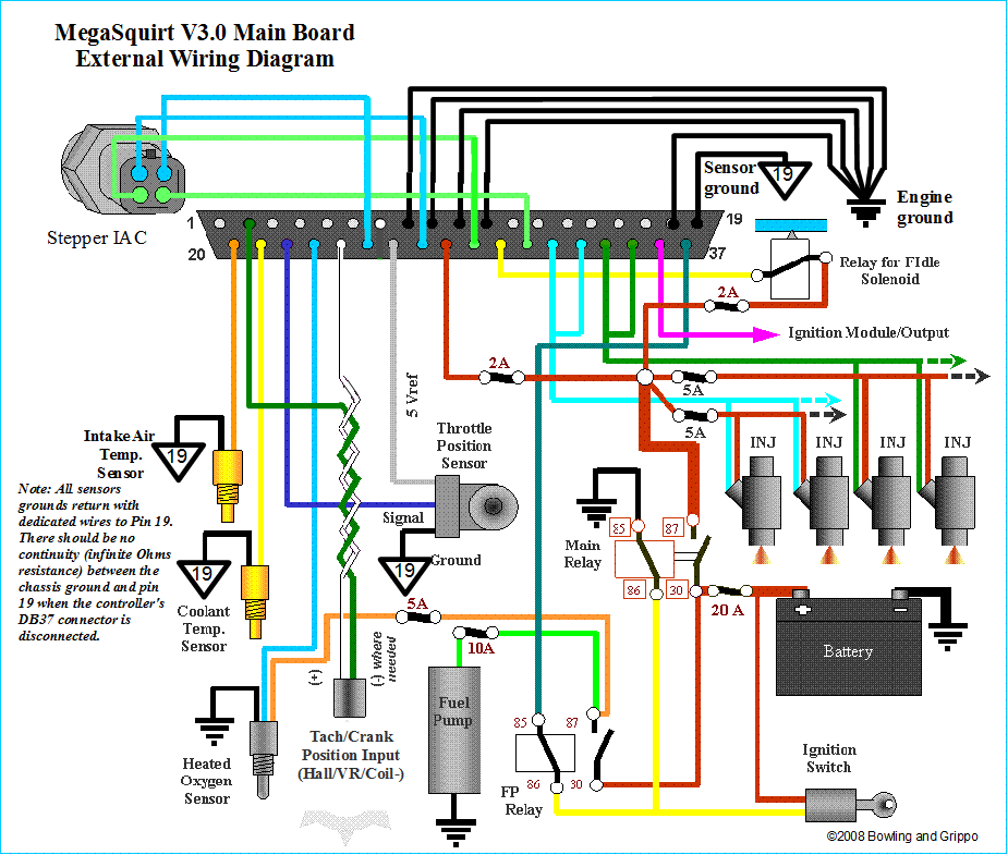
I am using an older DIY Autotune harness that uses a single wire crank position sensor wire. Wired the positive to PIN 24 and the shield to PIN 2. Similar to the image below:
Image

However I visited a friends house today, and he has a newer style shielded wire, one that runs the positive and negative and a shield. Similar to the image below:
Image

So is the single wire crank position signal outdated? I always thought that using the shielding as the sensor ground defeated the purpose of the shielding and the shielding should traditionally be grounded to the connector at the ECU end. However, I never had any sync issues running this for a few years.

If so, I have a bunch of this wire, and I am just making an 18" harness from the DB37 to a Subaru ECU connector, can I just run two of these wires for each crank and cam sensor, then solder the shields together underneath the DB37 body?

Also, since I will now be using PIN 1 for VR sensor grounds, do I need to do anything inside the MS to enable this?
DaveEFI
Super MS/Extra'er
Posts: 4175
Joined: Sun Apr 15, 2012 12:55 am
Location: SW London, UK

Re: Question about Crank/Cam VR Sensor Wiring, Shields, and

Post by DaveEFI »

Single wire tach connection is usually ok for a relatively high voltage source like a coil or EDIS module. A VR sensor produces a much lower voltage at low engine speeds - especially when cranking - so the norm is to use a twin and screen.

With all sensors the rule of thumb is to run both 'hot' and ground right the way back to the DB37 connector, and only connect the grounds together there - and to a pin or pins you dedicate to sensor grounds only. The power grounds go to different ground pins. (It doesn't much matter what ground pins are used - just keep sensor and power grounds separate within the connector. They are then commoned inside MS.
The VR cable screen isn't carrying any current since it is only connected at one end, so it doesn't much matter where it is grounded to at the DB 37.
Rover SD1 3.5 EFI
MS2 V3
EDIS
Tech Edge O2
London UK.
Post Reply