MS1 2nd trigger Cam sensor input and assembly
Moderators: jsmcortina, muythaibxr
-
cwdodson88
- Helpful MS/Extra'er
- Posts: 96
- Joined: Tue Apr 15, 2014 7:39 am
MS1 2nd trigger Cam sensor input and assembly
Hello all, My google fu seems to be weak today.
I'm trying to set up (or get my head wrapped around setting up) and MS1 for sequential COP and alternating bank fire injection using 2 hall geartooth sensors, one on a 36-1 wheel and one driven at cam speed with a single tooth mounted in a distributor.
This is on a 4 cylinder Volvo B20
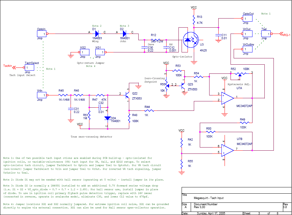
My understanding is that in order to do this I will need to duplicate the opto isolator circuit on a proto board and connect that from the sensor>opto circuit>js8 on the processor. But I'm not exactly sure how to build the circuit and what part#s will be needed to do this.
Sorry for bringing up MS1 but I dont really know which direction to go in.
-
Matt Cramer
- Super MS/Extra'er
- Posts: 17507
- Joined: Thu Apr 16, 2009 8:08 pm
Re: MS1 2nd trigger Cam sensor input and assembly
What board version?
Matt Cramer -1966 Dodge Dart slant six running on MS3X
-
cwdodson88
- Helpful MS/Extra'er
- Posts: 96
- Joined: Tue Apr 15, 2014 7:39 am
-
cwdodson88
- Helpful MS/Extra'er
- Posts: 96
- Joined: Tue Apr 15, 2014 7:39 am
Re: MS1 2nd trigger Cam sensor input and assembly
Basically I would reproduce the OPTO portion of this circuit (on a proto board or the proto area)

and connect:
opto-in to the sensor signal
xg1 to ground
vcc to 5v?
opto-out to whatever pin on the processor (js8 I think)
Does that make sense?

and connect:
opto-in to the sensor signal
xg1 to ground
vcc to 5v?
opto-out to whatever pin on the processor (js8 I think)
Does that make sense?
-
Matt Cramer
- Super MS/Extra'er
- Posts: 17507
- Joined: Thu Apr 16, 2009 8:08 pm
Re: MS1 2nd trigger Cam sensor input and assembly
Yes, duplicating that circuit is one way to do this.
Matt Cramer -1966 Dodge Dart slant six running on MS3X
Re: MS1 2nd trigger Cam sensor input and assembly
If your MS1 uses the V3 board, it already has two tach inputs - VR and Opto. The VR one can be used with a hall effect sensor too. Details in the manual. The convention these days would be to use the VR input for your crank sensor and the opto for the cam sensor.cwdodson88 wrote:3.0
Rover SD1 3.5 EFI
MS2 V3
EDIS
Tech Edge O2
London UK.
MS2 V3
EDIS
Tech Edge O2
London UK.
-
cwdodson88
- Helpful MS/Extra'er
- Posts: 96
- Joined: Tue Apr 15, 2014 7:39 am
Re: MS1 2nd trigger Cam sensor input and assembly
So I can use the VR circuit for a hall sensorIf your MS1 uses the V3 board, it already has two tach inputs - VR and Opto. The VR one can be used with a hall effect sensor too. Details in the manual. The convention these days would be to use the VR input for your crank sensor and the opto for the cam sensor.
Re: MS1 2nd trigger Cam sensor input and assembly
Think you'll have to look at MS2 instructions for how to use the VR input with a hall sensor - the MS1 instructions haven't really been updated. But the V3 board is the same for both.cwdodson88 wrote:So I can use the VR circuit for a hall sensorIf your MS1 uses the V3 board, it already has two tach inputs - VR and Opto. The VR one can be used with a hall effect sensor too. Details in the manual. The convention these days would be to use the VR input for your crank sensor and the opto for the cam sensor.I guess I didn't see or understand that part of the build instructions.... I'll try that I guess. Can you point me to that part of the manual? Will I need to adjust the POTS?
Set R52 fully anti-clock and start with R56 fully anti-clock too. I generally find R56 about 6-8 turns clockwise works best with a hall sensor. But you may have to experiment.
Rover SD1 3.5 EFI
MS2 V3
EDIS
Tech Edge O2
London UK.
MS2 V3
EDIS
Tech Edge O2
London UK.
-
cwdodson88
- Helpful MS/Extra'er
- Posts: 96
- Joined: Tue Apr 15, 2014 7:39 am
Re: MS1 2nd trigger Cam sensor input and assembly
Thank you sir! I didn't even think to look into the MS2 instructions... But if I can use an onboard circuit for both I'll be happy!DaveEFI wrote: Think you'll have to look at MS2 instructions for how to use the VR input with a hall sensor - the MS1 instructions haven't really been updated. But the V3 board is the same for both.
Set R52 fully anti-clock and start with R56 fully anti-clock too. I generally find R56 about 6-8 turns clockwise works best with a hall sensor. But you may have to experiment.