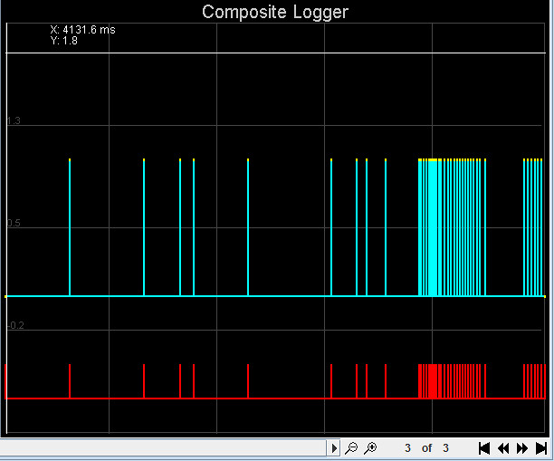
Can anyone give me any pointers as to what's giving me these results? This engine is yet to start, and the tach input is all over the place. The tooth logger gives me occasional returns at what seems like random intervals, and the trigger logger gives me nothing at all. Changing between rising/falling edge doesn't help. The composite logger below is taken with the trigger wheel (36-1) and sensor (1GT101DC) on a bench (I ran out of car batteries). I don't really know what causes sync loss like that.
I've definitely seen this setup producing a good tach signal in the past, but something has obviously changed. At one point, I stupidly connected the sensor earth line to 12V by mistake. Thinking I'd ruined the sensor, I replaced it with another one, but with the same results. Could I have damaged something inside the MS2?
MS2 is running v3.3.3. TSEL is jumpered to VROUT. TunerStudio is probably from before the release of v3.3.3 (on my list of things to try). I tried saving a datalog, but whenever I go to open it again, it just says it's empty
TIA.
Andy.
Last edited by AndyMV on Sat Jun 27, 2015 4:48 am, edited 1 time in total.
I tried saving a tooth log, but it just said the file was empty when I reopened it. It showed basically nothing when cranking, with a group of two or three pulses sporadically popping up.
Here's a tooth log, although I'm not sure how helpful it will be. Some playing with R52 & R56 has got me something looking slightly better, but certainly not right. R56 is now set quite high, which seems to go against a lot of what I've read. That was also necessary to get anything from the JimStim, set for VR out.
I'm a bit confused here. That "1GT101DC" is a Honeywell sensor, correct? That is a Hall-effect sensor, so why are you setting the JimStim to VR output? Does that sensor need an external pull-up and, if so, is it in place. Also, what is the scope trace showing (two channels, correct); your wording kind of flits back-and-forth between calling that both the sensor output and the JimStim output. How are the pots adjusted, R52 full CCW and R56 6-turns back from full CCW? Is the mainboard built from akit, maybe we better verify that the pots are installed correctly?
Yes, it's a Honeywell sensor. The JimStim was set to VR out while I was troubleshooting earlier. The tach signal is disabled now I've connected the sensor. The JimStim just gives me a convenient connection to the MS2.
The MS2 is wired for 5v pull-up. I think that's necessary for the GT1.
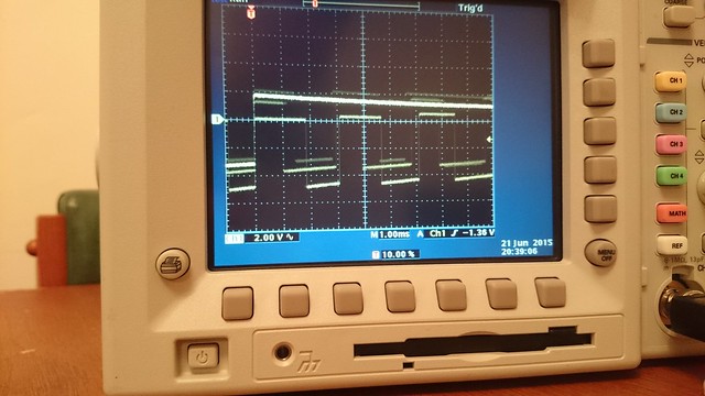
The scope is showing 1 channel.
The pots are adjusted how you mention, although adjusting them seems kind of pointless given the state of my input signal.
The board was built from a kit, but by someone who knows what they're doing (not me).
I've just ordered a Hamlin 55075 online out of frustration. I just hope there isn't an issue with the VR conditioner circuit.
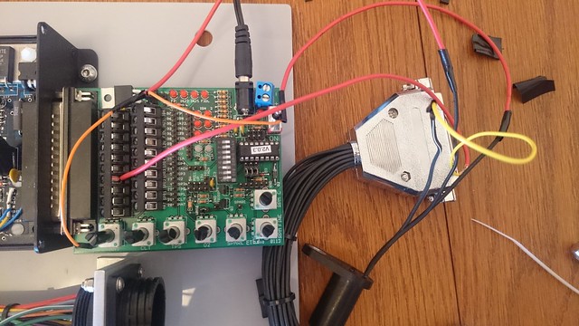
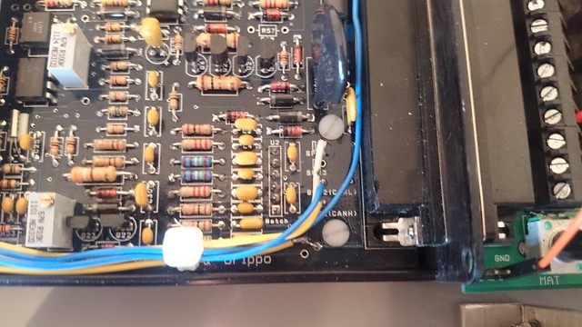
I suggest focusing on testing with the JimStim right now. Once you can get good tooth logs, sync, scope traces, etc. that way we will go back to the car. The advantages to focusing on triggering it from the JimStim is that it will eliminate possibilities of wiring problems for now, and there are many of us familiar with using a scope with it, we can guide you as to where to probe and what you should see. A good first step would be to post pictures of the JimStim so we can verify the switch and jumper settings on it are OK.
Okay, from the picture it looks like you have the JimSim DIP switch set correctly for 36-1 (only #3 "on").
It also looks like you are by-passing the JimStim wheel simulator and feeding the real CKP sensor input to the MS. I suggest using the JimStim wheel simulator, remove those extra wires and install the appropriate jumper-blocks on the JimStim. Once you have a good reliable tach signal that way, as evidenced by the loggers and no sync losses, then we can move on to making the actual CKP sensor work. Do you have two channels on the scope? If so, trigger the sweep off of the "2nd trigger" header pin on the JimStim, the single pin at the upper-right of the O2 pot. That will give you a nice clean scope sweep where two crank revolutions are displayed
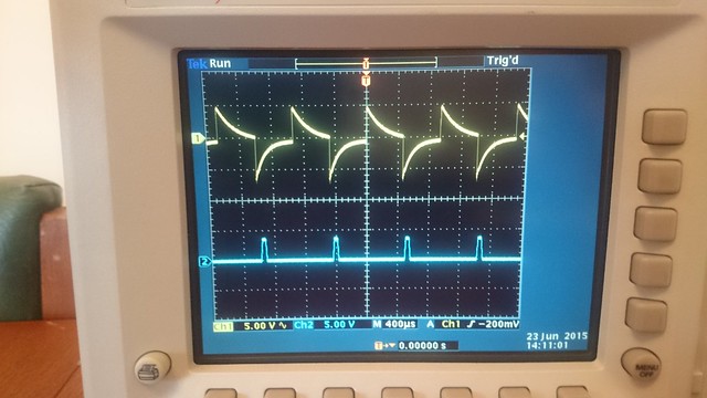
Here's what TachSelect (Ch1) and TSEL (Ch2) look like with the JimStim producing a signal:
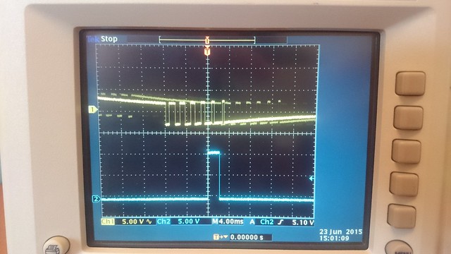
Here's what the GT1 looks like with 12V of pull-up. Ch2 is hooked to the second trigger pin like you suggested. Is this superimposed signal something I should worry about, or is it just my inability to use the scope correctly (quite possible)? Either way, the number of teeth shown obviously isn't right. It went up and down even with a steady RPM. This is with the sensor gap set to give the best signal.
I'll pick up my (second) Hamlin 55075 tonight and hook it up tomorrow. Hopefully that will help, but I'm not too optimistic.
Using the JimStim 2nd trigger for sync won't do any good when the primary (CKP) signal is coming from something other than the JimStim, like an actual sensor and wheel. On an actual engine you could use the CMP (cam) input to sync on, but that would be relying on the CMP signal as being good. With just a CKP wheel I have have pretty good luck syncing on that signal when the CKP sensor is VR. It seems that the tooth right after the missing-tooth gap has a higher amplitude than the others, so careful setting of the scope trigger level can catch that. Unfortunately, Hall sensors don't do that, so it is hard to sync the scope. I find it works better then to set the sweep rate kind of slow, so that several crank revolutions are displayed. They may be slowly "rolling by", but will be easier to understand than the "multiple trace" you are getting. Do you have a test wheel to use when looking at these CKP sensors, or does that all have to be done on the engine?
Edit: I noticed just now that you have four (color) channels on that scope, we can have lots of fun here!
Honeywell GT1 swapped out for a Hamlin 55505. It works
That GT1 obviously did not get on with my trigger wheel. I wrongly thought I was buying the same item when I replaced the original sensor, but although they look identical, they clearly have different internals. Lots of time wasted as I didn't realise I was comparing apples with oranges.
Before the 55505 arrived, I removed the internal 5V pull-up and set R56 to give a reading of 2.5V on R54. R52 is fully anti-clockwise. Everything now looks good in TunerStudio, and there is no pull-up on the JimStim. Hopefully it stays that way once I get it back on the engine.
Thanks for all the help Bill. And thanks to Mouser Electronics & FedEX for getting me a new sensor from Texas to Norfolk, UK in 2.5 days. That's rapid!