Relay control - Your GND and SPR4 are reversed; power flows from the relay on SPR4 to the transistor to ground.
FIdle - And this is why I like to use different coloured wires ... It looks like you have everything wired up, but where's your diode? That is your flyback catch diode, and should be going from the TIP120 collector to +12v (pad S12).
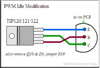
Take a look at the latest manual instructions; the pins selected have changed to use heavier traces. Make sure the tab on the TIP120 isn't shorting to the heat sink bar; burrs on the bar holes are infamous for causing all sorts of problems.
Temporarily shut down - back soon!
QuadraMAP Sensor Module -- PWM-to-Stepper Controller -- Dual Coil Driver
Coming soon: OctoMAP Sensor Module TTR Ignition Systems
your relay output will provide ground when its active. as to your idle valve have a peek here for the recommended method for putting it together inside the ecu
do you have the 3 wire valve? if so how have you got it connected up?
1990 bmw 320i daily driver with m20b25 ms3 sequential fuel, 380cc injectors, d585 coil near plug, home made cam sync, launch control, fan control, vss, homebrew egt logging what's next????
if you have done the tip120 you will only be able to control one side of the icv you will want a big 30-40 ohm 50w resistor between 1 winding and ground.
1990 bmw 320i daily driver with m20b25 ms3 sequential fuel, 380cc injectors, d585 coil near plug, home made cam sync, launch control, fan control, vss, homebrew egt logging what's next????
1990 bmw 320i daily driver with m20b25 ms3 sequential fuel, 380cc injectors, d585 coil near plug, home made cam sync, launch control, fan control, vss, homebrew egt logging what's next????