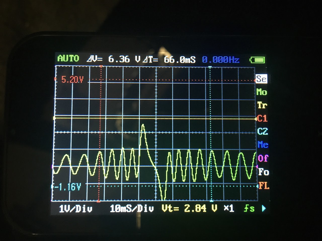
Given that I intend to start with only the stock igniter and distributor trigger, should I connect the distributor trigger to VR+ or VR2? I get the part about possibly needing to install R21, but how will I know if i need to do this? I assume that I will get inconsistent engine speed readings at idle and up to a certain RPM, if I understand correctly. Does this sound right?Variable reluctor sensors, sometimes called VR sensors, inductive pickups, or magnetic pickups, have two wires, and possibly a third shield wire. Connect the positive wire to VR+ and the negative wire to VR-. Sometimes it may take a bit of trial and error to find out which is which since factory wiring diagrams often do not mark these clearly. If you have a shield wire, connect it to GND. Tip: If your sensor is connected to a wheel with a large number of teeth, like a Ford 36-1 or a Bosch 60-2, and you're losing the tach signal at high RPM, put a 10K resistor in line with the wire going to VR+. This will usually clear things right up.
The camshaft position sensor input is marked VR2. It's actually a kind of hybrid circuit that works with Hall effect, VR, and optical sensors. Hall or optical sensors may need a pull up, just like with the crankshaft position input. VR sensors with a separate ground wire should have this wire connected to SG. The VR2 circuit has a built in threshold that some VR sensors may not trigger correctly at low RPM. If this happens on your car, take a 51K resistor and install it in the R21 position. This will lower the threshold voltage. Many Nippondenso ignitions will need this mod. For other sensors, you can install R39 to make the trigger voltage user-adjustable, or use R20 to pull up the trigger voltage to reduce noise.
Alternatively, I could put my energy into eliminating the igniter and distributor in favor of using the crank angle sensor and coil plugs if that would be simpler. This is ultimately what I would like to run, but I figured it would be easier to make use of the stock ignition stuff to get started and comfortable tuning. I would also need to buy the high current ignition drivers, since they are not included in the kit.
Sorry for the n00b questions, but I'm not finding a lot of detail around how to set this up with the DIYPNP kit. Any advice is greatly appreciated.
