ok i am at testing stage 13.5 of the ms3 board i looked over everything and all looks good to me.
i connect ny jim stim that i put together and was tested to the board and i power it on and i notice the power led starts to blink like it dims and comes back on is this normal?? is there something i have to have jumpered on the jim stim for it to work properly?? i have no jumpers on the jim stim itself i turned it off right away because i wasnt sure if that was normal or not. if not normal what could cause that??
ms3 assembly testing stage
Moderators: jsmcortina, muythaibxr
-
eddy_amaya08
- MS/Extra Newbie
- Posts: 15
- Joined: Tue Dec 27, 2016 4:44 pm
-
eddy_amaya08
- MS/Extra Newbie
- Posts: 15
- Joined: Tue Dec 27, 2016 4:44 pm
Re: ms3 assembly testing stage
Checked the 12v pin when this is happening and voltage is fluctuating between 1.9v and 4v any idea why?
-
billr
- Super MS/Extra'er
- Posts: 6828
- Joined: Sun May 15, 2011 11:41 am
- Location: Walnut Creek, Calif. USA
Re: ms3 assembly testing stage
What are you powering the Stim with? What is the 12V when the MS isn't connected to the Stim?
-
eddy_amaya08
- MS/Extra Newbie
- Posts: 15
- Joined: Tue Dec 27, 2016 4:44 pm
Re: ms3 assembly testing stage
The power supply they sell on their site and without the board connected it reads normal 12v
Re: ms3 assembly testing stage
Check your diode polarity, it sounds like you may have 1 or more installed backwards.
Linfert Performance/321 Motorsports
SCCA 2019 SM National Champion Crew Chief
SCCA 2023 FP National Champion Tuner/electrical engineer
100s of MS systems built installed and tuned
Support the developers!
SCCA 2019 SM National Champion Crew Chief
SCCA 2023 FP National Champion Tuner/electrical engineer
100s of MS systems built installed and tuned
Support the developers!
-
eddy_amaya08
- MS/Extra Newbie
- Posts: 15
- Joined: Tue Dec 27, 2016 4:44 pm
Re: ms3 assembly testing stage
Checked all diodes and lol facing the correct way so not that
Here is the board
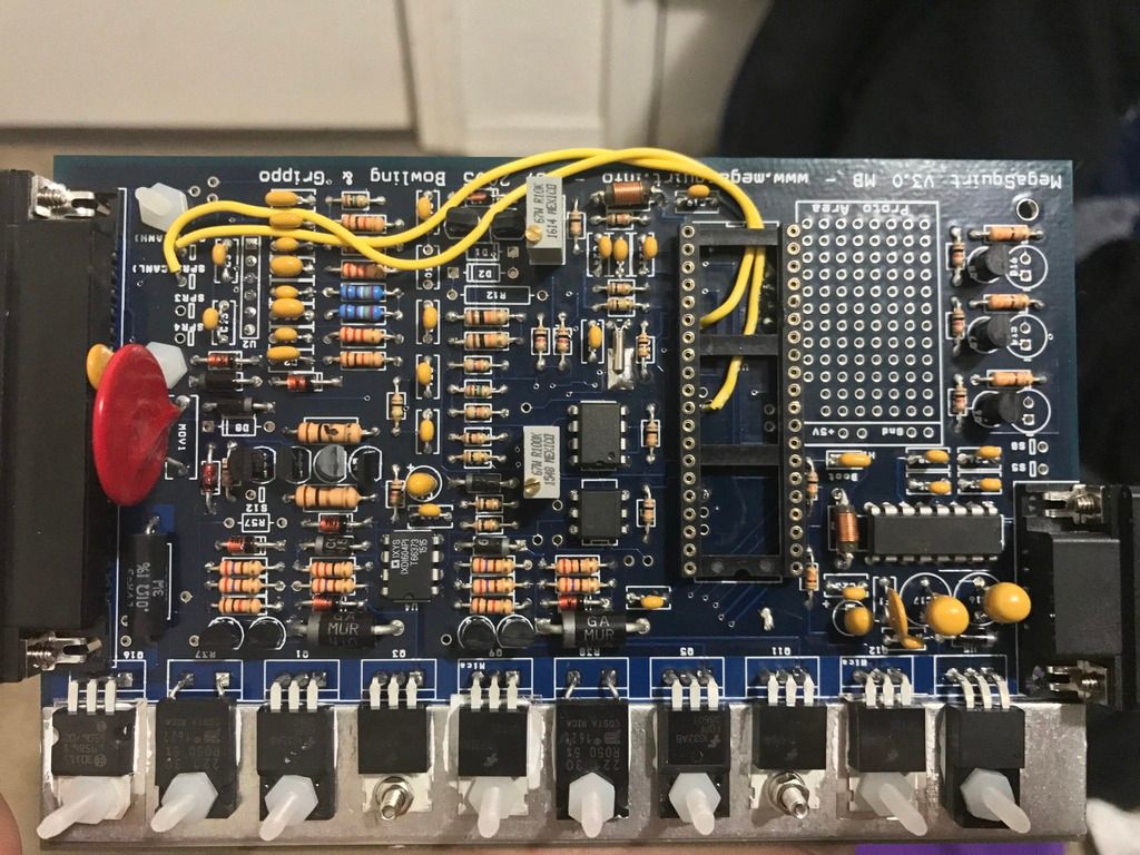
Here is the board

Re: ms3 assembly testing stage
If you power up the JImStim without it plugged into the MS, is the power LED on it OK?
Rover SD1 3.5 EFI
MS2 V3
EDIS
Tech Edge O2
London UK.
MS2 V3
EDIS
Tech Edge O2
London UK.
-
eddy_amaya08
- MS/Extra Newbie
- Posts: 15
- Joined: Tue Dec 27, 2016 4:44 pm
Re: ms3 assembly testing stage
Yes it is normal it's only with the board connected
Re: ms3 assembly testing stage
Right. And the power LED on the Stim is showing this without the MS2 daughter card plugged in?
Have you also double checked the polarity of the tantalum caps?
Have you also double checked the polarity of the tantalum caps?
Rover SD1 3.5 EFI
MS2 V3
EDIS
Tech Edge O2
London UK.
MS2 V3
EDIS
Tech Edge O2
London UK.
-
eddy_amaya08
- MS/Extra Newbie
- Posts: 15
- Joined: Tue Dec 27, 2016 4:44 pm
Re: ms3 assembly testing stage
The stim led is normal when the mscard isn't plugged in it only blinks when the ms card is plugged in.
And what are tanatalum caps??
And what are tanatalum caps??
-
billr
- Super MS/Extra'er
- Posts: 6828
- Joined: Sun May 15, 2011 11:41 am
- Location: Walnut Creek, Calif. USA
Re: ms3 assembly testing stage
Are you saying there is no change if the daughterboard is not installed on the mainboard; the mainboard alone disrupts 12V?
The tantalums are the caps that look like "gum-balls", not flat disks. More telling... they will have a "+" or "-" marking to show which way they should be. C16, C17, & C22 are the ones I see with a quick peek at the schematic.
The tantalums are the caps that look like "gum-balls", not flat disks. More telling... they will have a "+" or "-" marking to show which way they should be. C16, C17, & C22 are the ones I see with a quick peek at the schematic.
-
eddy_amaya08
- MS/Extra Newbie
- Posts: 15
- Joined: Tue Dec 27, 2016 4:44 pm
Re: ms3 assembly testing stage
The main board alone disrupts the 12v I have not got past step 13.5 which is testing of the main board.
I checked the side marked positive is on the side where it's shows positive on the board so I assume
That's right
I checked the side marked positive is on the side where it's shows positive on the board so I assume
That's right
Re: ms3 assembly testing stage
The power led fading in and out suggests a cap charging and discharging.eddy_amaya08 wrote:The main board alone disrupts the 12v I have not got past step 13.5 which is testing of the main board.
I checked the side marked positive is on the side where it's shows positive on the board so I assume
That's right
I think you're going to have to isolate parts of the circuit by removing components to find out where the problem lies, referring to the power supply schematic. I'd start by removing the polyfuse FI. The difficulty with this is avoiding doing damage to the PCB.
Rover SD1 3.5 EFI
MS2 V3
EDIS
Tech Edge O2
London UK.
MS2 V3
EDIS
Tech Edge O2
London UK.
-
billr
- Super MS/Extra'er
- Posts: 6828
- Joined: Sun May 15, 2011 11:41 am
- Location: Walnut Creek, Calif. USA
Re: ms3 assembly testing stage
I suggest posting pictures showing the whole board, and both sides. That may not show any problem, but removing/disconnecting components can result in damage to the board, as warned above. If you do have to remove/disconnect, I suggest cutting leads so that they (the through-hole leads) can be removed one-by-one. The components may have to be sacrificed, but are cheap and it is much easier to replace them than fix a damaged board. I pull such leads by attaching a small locking-tweezers (hemostat) to the lead so that the weight is hanging from the solder joint. As soon as the solder is hot enough to melt, the weight pulls the lead free cleanly with minimum heating of the board.
-
eddy_amaya08
- MS/Extra Newbie
- Posts: 15
- Joined: Tue Dec 27, 2016 4:44 pm
Re: ms3 assembly testing stage
The picture I posted is the whole Board just have to click on it and it will show it all and I can post one of the rear as well
Re: ms3 assembly testing stage
One of the most common places to have shorts is on the small transistors as their pads are very close together.eddy_amaya08 wrote:The picture I posted is the whole Board just have to click on it and it will show it all and I can post one of the rear as well
If you have a pal who is good at electronics, it can help to have a fresh pair of eyes to look things over.
Rover SD1 3.5 EFI
MS2 V3
EDIS
Tech Edge O2
London UK.
MS2 V3
EDIS
Tech Edge O2
London UK.
Re: ms3 assembly testing stage
Hi, any update or resolution, because i am having the same probleme.
Regards
Paul
Regards
Paul
-
billr
- Super MS/Extra'er
- Posts: 6828
- Joined: Sun May 15, 2011 11:41 am
- Location: Walnut Creek, Calif. USA
Re: ms3 assembly testing stage
Same problem? Then same suggestion, post (good) pictures of both sides of the mainboard; let's start with a visual inspection.
Re: ms3 assembly testing stage
After more testing, i fund out that JIMSTIM is sending out 2V on pin 28 ( my MS3 board probably damaged my stim ).
When i power MS3 board thrue pin28 and ground, i blow the 3 amp fuse.
Did the tests that where recomemnded
( diodes are all the right way, Q9 and Q12 are not grounded, cannot see any solder bridges , C16 17 22 and 14 are on the right way also )
I toke some pics.
Should i start a new thread
Paul
When i power MS3 board thrue pin28 and ground, i blow the 3 amp fuse.
Did the tests that where recomemnded
( diodes are all the right way, Q9 and Q12 are not grounded, cannot see any solder bridges , C16 17 22 and 14 are on the right way also )
I toke some pics.
Should i start a new thread
Paul
-
billr
- Super MS/Extra'er
- Posts: 6828
- Joined: Sun May 15, 2011 11:41 am
- Location: Walnut Creek, Calif. USA
Re: ms3 assembly testing stage
Yes, please start a new thread! I suggest cutting/pasting your previous posts (here) into the new thread.