I generate rectangles (0V - 5V) using an Arduino to emulate a crank sensor (VR input mainboard, 24-1 wheel) and a cam signal (MS3X cam input).
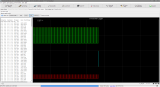
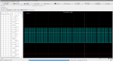
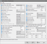
This is a composite log of it working correctly and the ignition settings in the MSQ:
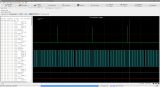
The cam signal works perfectly all the time. However, the crank signal only works occasionally and I can't figure out why.
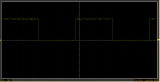
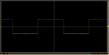
Using an oscilloscope on TSEL, I can see the signal is not triggering the VR signal when it's not working. There's just nothing there. Changing the pots (R52/R56) does not change anything, and I left them fully "open" as recommended. If it does work (power cycling everything several times), it mirrors the input signal perfectly and works flawlessly until power cycling again.
Is there something I'm missing? I looked at other threads mentioning something like this, but from what I understood this is only a common problem with dual VR boards and not with the standard VR circuit.
Grounding the microcontroller on the MS and even powering it directly via the MS does also not seem to make a difference.