Measuring Driveshaft Torque
Yes I know this is available in professional grade and AEM used to offer the "dynoShaft". But what about this?
Two trigger wheels at each end of the driveshaft. OR even use the crank trigger and a driveshaft trigger. Then you measure the twist in the shaft by the difference in timing between each tooth. From my research aluminium driveshafts can twist +30 degrees! so this should be measurable with simple hall effect sensors and wheels.
Seems like it should be easy enough to build with a couple of wheels and hall sensors. Getting super fast timing would critical so some fancy code would be needed to get very precise angles.
Thoughts? Discussion? Lunatic?
Measuring driveshaft torque
Moderators: jsmcortina, muythaibxr
-
turbo conversion
- Super MS/Extra'er
- Posts: 1281
- Joined: Thu Aug 19, 2010 6:22 pm
- Location: White House, TN USA
Re: Measuring driveshaft torque
You would need the deg. vs torque specs for a lot of drive shafts.
If that is easily available then I guess it could work
David
If that is easily available then I guess it could work
David
1976 Datsun 280Z L28ET Garrett GT35R T3-T04E stage3 50 trim 63 A/R housing custom grind cam 2000-6000 rpm 440cc injectors intercooled 18 lbs. boost
3" exhaust turbo back LC-1 o2 sensor Hallman manual boost controller EDIS 6 ignition batch fire 60mm throttle body 5 spd T5 borg warner 3.54 lsd
3" exhaust turbo back LC-1 o2 sensor Hallman manual boost controller EDIS 6 ignition batch fire 60mm throttle body 5 spd T5 borg warner 3.54 lsd
Re: Measuring driveshaft torque
Not necessarily.. the numbers are all comparative anyway. When dyno tuning your maximizing torque right? So all you need to do is maximize driveshaft twist.turbo conversion wrote:You would need the deg. vs torque specs for a lot of drive shafts.
Would it be accurate enough to detect a difference of 5ft-lb, idk. Might be worth testing unless anyway can tell me otherwise?
-
billr
- Super MS/Extra'er
- Posts: 6828
- Joined: Sun May 15, 2011 11:41 am
- Location: Walnut Creek, Calif. USA
Re: Measuring driveshaft torque
Sure, that can work. That system has been used on T56 aircraft turbine engines since the 1950's. Or, a similar meter could be made with wheels that flex a bit. Every time I get enthused about making such a beast, I come back to the question of what I would do with it. For racing it might be great to see the drive torque at various places/conditions on the track. And, if it was a wheel system you could also see braking. However, for me, I would want to be using it as a "dyno" and would need to hold steady-state conditions. That is near impossible on public roads. For personal purposes I never felt calibration is a big issue, some simple measurements and then a LUT would work no matter how non-linear the system was. Even for a production item cal may not be bad, torsion characteristics for round shaft/tubes have been well-researched and documented. I'm not trying to dismiss your idea, just pointing out some of my thoughts on it. I have focused more on a wheel system, since it would work without needing and "open" drive-line and would give braking torque too. Also, it could be easily shared with others.
-
racingmini_mtl
- Super MS/Extra'er
- Posts: 9130
- Joined: Sun May 02, 2004 6:51 am
- Location: Quebec, Canada
- Contact:
Re: Measuring driveshaft torque
Plenty of people use inertia dyno for tuning so that would be equivalent.
And regardless of how you calibrate or if you even need to, using a wheel at each end of the driveshaft would be the simplest thing to do if you use a wheel with teeth that are spaced by more than the maximum torsion angle of the driveshaft. That way you can just use one internal timer to compare what the time difference is between one edge on the first wheel and one edge on the second wheel. You don't need to know the absolute edge position (no wheel decoding) and you can use simple toothed wheels. You also need to calibrate the no-load offset because you're not likely to have the 2 wheels and sensors perfectly aligned with each other.
So the edge-to-edge time on the same wheel gives you RPM and the edge-to-edge time between wheels (minus the calibrated offset) gives you the torque (however you want to calibrate it).
If you want to use smaller wheel teeth for greater accuracy, you then complicate things because now you would need missing tooth wheels and wheel decoding to know the number of teeth in the offset you have for the current shaft torsion in addition to the edge time offset. That also means you have to re-sync each time you stop and go and you also need to identify if you've missed teeth and when you stop and when you need to sync and ... Wheel decoding is a lot messier.
Jean
-
whittlebeast
- Super MS/Extra'er
- Posts: 2221
- Joined: Tue May 04, 2004 8:20 pm
- Location: St Louis
- Contact:
Re: Measuring driveshaft torque
Ford does that on their long term durability testing of prototype cars. They pull heavy trailers up and down mountains in a huge driving loop watching for drops in torque.
Andy
Andy
Re: Measuring driveshaft torque
Novel idea and if you attempt to test, hope it provides usable results.jacky4566 wrote:Measuring Driveshaft Torque
Yes I know this is available in professional grade and AEM used to offer the "dynoShaft". But what about this?
Two trigger wheels at each end of the driveshaft. OR even use the crank trigger and a driveshaft trigger. Then you measure the twist in the shaft by the difference in timing between each tooth. From my research aluminium driveshafts can twist +30 degrees! so this should be measurable with simple hall effect sensors and wheels.
Seems like it should be easy enough to build with a couple of wheels and hall sensors. Getting super fast timing would critical so some fancy code would be needed to get very precise angles.
Thoughts? Discussion? Lunatic?
However, and from a standpoint of driveline tech and torsional studies (at our work, we perform a torsional analysis on every class 8 machine manufactured) - shaft twist is not exactly something you want to foster, and if certain aluminum versions will allow 30 degrees of wind up, that would be hopefully the exception and not the norm for a vehicle you expect to pour the coals to on a regular basis and not destroy the driveline. Torsional vibrations are particularly hard on automatic trannys where larger rotating clutch drums can see aggressive tang and grove wear between plates and drums. Of course, other items like "U" joints and axle gear sets are also at risk (although tires do serve to absorb an alarmingly high amount of torsionals themselves also.)
This is however, academic and certainly nothing new in the automotive sector. I guess the point offered is that the measurable shaft twist on a less flexible (or fragile) set up might (hopefully is) far less.
1983 BMW R100RT Motorbike
Turbocharged - Water/Meth
Sequential Ignition & Fuel
"Perky Sleeper" that excites bike enthusiasts once discovered (or being passed)
Newest project - 1995 BMW K75 is V3 Microsquirt, "Turbocharger - Of Course"
Turbocharged - Water/Meth
Sequential Ignition & Fuel
"Perky Sleeper" that excites bike enthusiasts once discovered (or being passed)
Newest project - 1995 BMW K75 is V3 Microsquirt, "Turbocharger - Of Course"
-
pmbrunelle
- Helpful MS/Extra'er
- Posts: 103
- Joined: Mon Jun 06, 2011 1:21 pm
- Location: Montréal, Canada
Re: Measuring driveshaft torque
Measuring the deflection of a thin torsion bar is what many EPS units do to measure user torque.
In order to get a measureable amount of angle difference, the torsion bar needs to be thin. But thin means that the ultimate strength is low; therefore, you have hard stops saturating the angle travel (and thus torque readout) prior to torsion bar damage.
So rather than this silliness, why not just glue strain gauges to your driveshafts? But then they're turning... so you need some wireless interface.
The strain of a steel tube/cylinder is 1st-year university degree stuff; quite simple, no computerised calculations required.
But why focus on the driveshaft when tractive effort at the contact patches is what makes your car accelerate anyway?
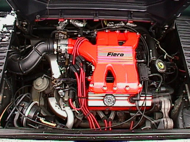
My personal car has a standard transverse powertrain, with the engine+trans bolted together. A "dogbone" mount up high on the engine handles the torque reaction of the engine powertrain assembly. So I would replace the dogbone with an S-beam load cell and two heim joints.
See dogbone strut, bottom-right of image:
But for the kind of tuning I want to do, I figure that it would be suicidal to do it while driving...
Since the time I had these silly ideas, I found a shop with a Dynapack.
In order to get a measureable amount of angle difference, the torsion bar needs to be thin. But thin means that the ultimate strength is low; therefore, you have hard stops saturating the angle travel (and thus torque readout) prior to torsion bar damage.
So rather than this silliness, why not just glue strain gauges to your driveshafts? But then they're turning... so you need some wireless interface.
The strain of a steel tube/cylinder is 1st-year university degree stuff; quite simple, no computerised calculations required.
But why focus on the driveshaft when tractive effort at the contact patches is what makes your car accelerate anyway?
My personal car has a standard transverse powertrain, with the engine+trans bolted together. A "dogbone" mount up high on the engine handles the torque reaction of the engine powertrain assembly. So I would replace the dogbone with an S-beam load cell and two heim joints.
See dogbone strut, bottom-right of image:
But for the kind of tuning I want to do, I figure that it would be suicidal to do it while driving...
Since the time I had these silly ideas, I found a shop with a Dynapack.
Re: Measuring driveshaft torque
Cool. Thanks for the constructive input. Ill ponder this a bit more and research those solutions presented.