5.0Thunder wrote:...First hiccup: Pigtail connector that I bought is backwards.. The "Keyed" slot on the connector is on the wrong side so my maf won't plug in. Everything else appears to be identical and most other connctors I see appear to have the slot in the right location sooooo I'm probably going to source a different one (ron francis maybe). I wish I had a scrap yard nearby that I could snip one out of.
Are you saying it won't plug in at all? All the Ford slot styles should be the same. You'll have to provide pictures.
Are you talking about an adapter harness to the early maf sensor or a pigtail connector to splice in?
I inded up cutting a channel out of the connector body so the plug would slide over the maf. It works okay and locks in correctly. It also has the weatherpack seal that should still be effective so it could work as-is.
1. The connectors look exactly the same in those pics. Doesn't matter, you fixed it.
2. Your MAF housing didn't have a flange? Mine doesn't have one & can't use one.
You could have purchased one with a flange for less than the welding will cost.
$17.49 https://www.spectreperformance.com/sear ... ?prod=8146
Blown88GT wrote:1. The connectors look exactly the same in those pics. Doesn't matter, you fixed it.
2. Your MAF housing didn't have a flange? Mine doesn't have one & can't use one.
You could have purchased one with a flange for less than the welding will cost.
$17.49 https://www.spectreperformance.com/sear ... ?prod=8146
1. Top left corner of plug in the first pic, top right corner of plug in the 2nd pic. The slot is on a diff corner in each pic.
2. That spectre flange won't work for me. That's what you would mount an existing maf housing on to, which I don't have. I'm sticking the sensor into my existing tube using the welded maf mounting "pad" or "flange" directly on the tube. it's simple, clean, and should work well. we'll see!
I did a conversion a while back by mounting an early 00' element into a 3in pipe. I just drove around a dataloged the ADC value and then did some math to find a rough g/s value. You only need a dozen points to start the curve.
g/s = (inj duty cycle% * total fuel flow * AFR) *454 / 3600 find the fuel flow in lb/hr X by 454 grams per gallon then divide out an hour to seconds.. 3600. AFR is the ratio of air to fuel.
200 lb/hr fuel flow * 13.0 AFR * 454 / 3600 is 327 g/s air flow.. 327/0.8 is 408HP. 200lb/hr / 0.5 BSFC is roughly 400HP.
306 SBFord, Torquer II EFI intake, 60 lbs injectors, 8 LS2 coils, VS Racing 7668 turbo, 4R70W, MS3x fw1.4 w/built in trans controller.
I believe I have a pretty decent transfer function already. I'll see how it does once I get the sensor wired up and running.
update: New flange weldment finished and tube/sensor is installed. I now have to wire the sensor to my ECU and start playing. Currently looking in the manual for which MS2 pins to use. Hopefully I have that done today and the car running on maf by this evening!
Aaaaannddd halted. Didn't know I had to build a circuit for MAF signal input soo this isn't getting done today. My local radioshack closed so I'll be waiting for an online order of resistors and caps.
The MAF Sensor measures the actual mass air-flow into the engine. This can be used for a more accurate
fueling calculation- other fueling algorithms estimate the mass air flow based on MAP, TPS, RPM, MAT.
MS2/Extra supports voltage MAFs only. Frequency MAFs (such as LS1) are not supported.
The sensors have at least three wires, 12V supply, Ground (sensor ground return) and signal to the Megasquirt.
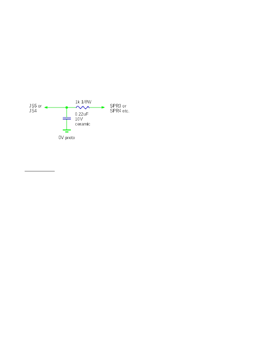
To connect a MAF to MS2/V3.57 internal hardware modifications are required. You may choose from either pin
'JS5 (ADC6)' or 'JS4 (ADC7)' so long as the input port setting in TunerStudio is set to match.
Externally you choose which pin on the main connector is used. Typically SPR3 or SPR4 would be used if they
are free.
Parts required. 1k 1/8W (or 1/4W) resistor. 0.22u 10V ceramic capacitor.
Solder onto some prototype board. Run jumper wire to JS5 or JS4 (your choice.) Run jumper wire to SPR3 or
SPR4 (your choice.)
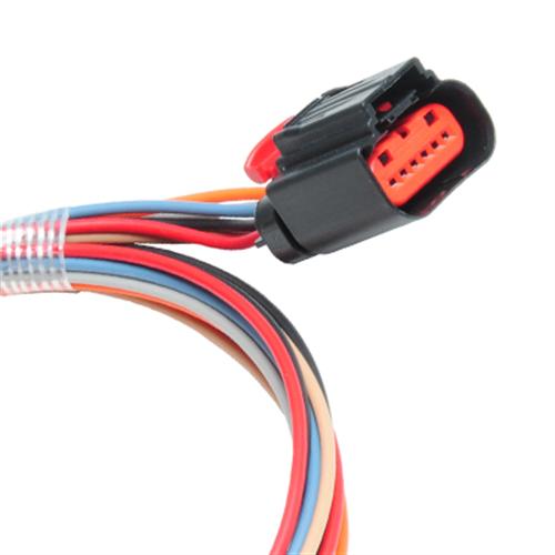
Ford 4 pin MAF
This earlier style MAF has an oval connector.
A = Switched 12 volts supply
B = Power Ground
C = MAF signal ground
D = MAF output signal
Alright so I got it all installed and running. It definitely is much harder to start due to poor initial fueling. At first it needed a LOT of warmup enrichment but in the end i found that my transfer function was off so that could have screwed the warmup enrichment.
I had to grab my whole function and shift it up 2g/s to get the warm engine to idle. AFR fluctuated pretty drastically but it made the lower end of the curve non-exponential so that's bothering me.
I'm wondering if it's be better to stick with the exponential function and just trim the entire VE table a certain % until idle is in range and go from there.
5.0Thunder wrote:...I'm wondering if it's be better to stick with the exponential function and just trim the entire VE table a certain % until idle is in range and go from there.
Yes. But start with the lower left cells & add 10-20% (110-120). If you can get it to idle on it's own, after WUE, go to Tune Analyzer Live tab & let it auto tune. Then drive it around while in auto tune.
Don't forget to change General Settings
Primary Fuel Load - MAF
Primary Ignition Load - Speed Density
AFR Table Load - MAP
EAE Curve Load - MAF
There could be some settings in closed-loop that need to be fine tuned.
I may be missing some other MAF settings for you.
Add Mass Air Flow to your gauge cluster so you are sure it is being read.
This is my VE Table after auto tuning while idling a cruising. Only got into a little bit of boost in the 2000-3500 rpm range. Yes, I can actually make some boost (1-2 lbs) with WOT at 2000 rpm.
Blown88GT wrote:
Yes. But start with the lower left cells & add 10-20% (110-120). If you can get it to idle on it's own, after WUE, go to Tune Analyzer Live tab & let it auto tune. Then drive it around while in auto tune.
My idle cells started around 130 then I got up to about 150 when engine was warm. No idea why it wants more fuel when hot.
Blown88GT wrote:
Don't forget to change General Settings
Primary Fuel Load - MAF
Primary Ignition Load - Speed Density
AFR Table Load - MAP
EAE Curve Load - MAF
Had these wrong so I changed them to your settings, we'll see how that goes tomorrow.
I attached an MSQ for reference and you can see how much fuel is there at idle. Having those settings wrong (above) could have played a role in some of this so the msq may not be much to look at. i'll see what changes tomorrow.
well I couldn't wait so I added your settings and also used the MAT correction table to keep the AFR correct as the engine warmed. Feels much more crisp now, gonna do some more tuning tomorrow if I get a chance.
More General Settings to change:
Multiply MAP - Don't Multiply
Stoich...AFR - Why 9.8??? You're using this value in your Required Fuel Calculator.
Still using standard Injector Dead time? Thought you changed this a long time ago.
Only 4 injectors on a V8 engine. Confused.
Ignition settings:
Fixed duty instead of standard dwell
27deg of initial timing at idle seems like a lot.
ASE - Immediately after the engine has started it is normal to need additional fuel. This curve specifies how much fuel
is added as a percentage – usually (5 to 50%)
Your ASE only goes to 25%.
Cranking pulse % curve looks bad.
All the Startup curves work best if linear.
Still in open-loop so I'll skip that.
Yeah you're going to have to forgive that tune, I really shouldn't have posted it. lol I had a lot of crap thrown in to those ASE and WUE curves when I was attempting to see what it wanted. I even had idle valve duty weird at one point. Haven't fixed them yet.
I changed to don't multiply.
high low RPM timing is like a wall to keep it from stalling currently.
This setup is not the same as the one where you helped me with the injectors. That one was an MPFI turbo car.
This one has four 160's in a 4bbl throttle body above a roots blower so it has the old standard numbers. They're low imp. 160's so they're driven with PWM. it's on e85 so that's where the req'd fuel stoich comes from. I know it looks weird, but that's how to set it up.
Ignition is ECU triggering MSD 6AL connected to coil. input is from a VR sensor in the distributor. The manual calls for standard dwell and not fixed duty on this type of setup.
Tomorrow should be a better tuning session now that the settings are corrected. The fuel and ignition load settings that I changed earlier already made a big difference, along with the MAT correction.
You current MAF Flow Curve doesn't look like the ones discussed on pg. 1 of this thread.
Did you do this first? Get the curve from MS3?
"...just pointing out that ms3 firmware ships with a lightening(sic) curve that can be transfered over and that a slot in a 4" od pipe is nearly identical..."
"...the flow data is in the ms3 firmware download look in tune files folder and there will be an msq.part you can open and it populates an open ms3 tune in tuner studios..." MS3 Lightning data
0.000 0.00
0.080 0.00
0.160 0.04
0.230 0.15
0.310 0.33
0.390 0.62
0.470 1.02
0.550 1.54
0.630 2.20
0.700 3.02
0.780 3.99
0.860 5.13
0.940 6.45
1.020 7.95
1.090 9.66
1.170 11.56
1.250 13.68
1.330 16.02
1.410 18.59
1.490 21.39
1.560 24.44
1.640 27.73
1.720 31.28
1.800 35.09
1.880 39.17
1.960 43.53
2.030 48.17
2.110 53.10
2.190 58.32
2.270 63.84
2.350 69.67
2.420 75.81
2.500 82.26
2.580 89.04
2.660 96.15
2.740 103.59
2.820 111.37
2.890 119.49
2.970 127.97
3.050 136.80
3.130 145.99
3.210 155.54
3.280 165.46
3.360 175.76
3.440 186.44
3.520 197.51
3.600 208.96
3.680 220.80
3.750 233.05
3.830 245.70
3.910 258.76
3.990 272.22
4.070 286.11
4.140 300.42
4.220 315.15
4.300 330.31
4.380 345.91
4.460 361.95
4.540 378.43
4.610 395.35
4.690 412.73
4.770 430.57
4.850 448.86
4.930 467.62
Don't know why these are so different unless the 2nd group is using the PMAS (or unspecified) housing?
Back to what I said earlier:
It's critical that whatever transfer function you use has the same sensor & same housing that you intend to use.
You need to be close before auto-tune can correct. If it doesn't work at all before auto-tune, it's not close enough.
The lightning transfer data won't work for me since I have the GT500 sensor. Those values you pulled for the GT500 sensor aren't converted to G/S so you have to do a conversion (I did in excel). I couldn't get the PMAS guy to tell me what size tube that sensor was tested in so that was always in the back of my mind. Then I found a function for the same sensor but in a 4" tube from VMP so I took that function, applied the conversion factor from 4" to 3.5" and used that instead. The curves ended up being pretty close but that's what I kept and started working off of.
Just a small update by my God guys, this MAF has made the car so much easier to drive and tune! I've had great luck with Speed Density on other port injected cars (NA and Turbo) but this carb style roots blower with TBI on top has been a tough deal with Speed Density. This MAF converstion has made it start and drive like any normal car now, with the exception of some enrichment tweaking that I'm doing. Clean tip-in, response, cruise without bucking, clean revving and decal, doesn't stall ever, making me pretty happy. lol
Here's something I haven't wrapped my head around.
Primary fuel load is MAF so the Y axis is MAFload.
Primary Ignition load is MAP so that ignition is controlled in relation to manifold pressure/boost.
My datalog graph shows MAFload going to 250ish while MAP goes to 160ish, yet the tuning window shows both fuel and ignition tables smashing the 200+kpa cells.
I'll have to rescale my fuel table for the higher maf load but shouldn't the ignition table just follow the MAP values?