4R70W diagram, work in progress 5.0/4r70w tacoma

'Microsquirt' Transmission Control development and support.

Moderators: jsmcortina, muythaibxr

Post Reply
blown5.0tacco
Helpful MS/Extra'er
Posts: 42
Joined: Wed Aug 02, 2017 9:12 am
Location: Dirty Jerzy

4R70W diagram, work in progress 5.0/4r70w tacoma

Post by blown5.0tacco »

i emailed DIY Autotune and talked to tech support to make me feel better i guess lol about answering my questions. looks like this is it for now, hopefully if anyone else has a 4r70w swap and they wanna use this it will help out, just keep in mind that i have the second microsquirt for the engine and dont need to connect the TCU to things like TPS, and Coolant Temp. maybe i can make up a diagram like they did in Illustrator or something too.

i have a 2001 toyota tacoma that i swapped this into, 5.0 supercharged gt40 explorer motor with 4R70W transmission and manual transfer case. im sorry if this seems like a lot to ask, im reading and i dont see a lot of people doing this so i dont have a lot to go off of. id like to know what some of these other wires go to, and i have a few questions at the bottom.

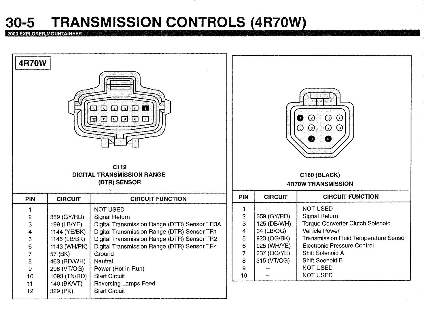
On my 2000 Ford 4R70W transmission this is what i have so far and or have assumed correct:

1. 12v Switched Power.........................................(12v key on power, splice in from other microsquirt ms3 engine controller)
2. CAN High.....................................................(connect to CAN High on other ms3 engine controller)
3. CAN Low......................................................(connect to CAN Low on other ms3 engine controller)
4. Engine Input Shaft Speed (+ VR2)..........................
5. Spare Analog Imput..........................................
6. Brake Switch Imput..........................................(brake pedal switch {GROUND not positive})
7. Shift Solenoid B...............................................Shift Solenoid B................................(C180 pin #8)
8. Shift Solenoid A...............................................Shift Solenoid A................................(C180 pin #7)
9. Torque Converter Control....................................Torque Converter Clutch Solenoid.......... (C180 pin #3)
10. Line Pressure Ctrl Solenoid.................................Electronic Pressure Ctrl...................... (C180 pin #6)
11. Selector Input B............................................. DTR tr2......................................... (C112 pin #5)
12. Selector Input A............................................. DTR tr1......................................... (C112 pin #4)
13. serial RX......................................................N/A
14. serial TX......................................................N/A
15. Bootloader....................................................
16. Shift Solenoid D............................................. N/A
17. Shift Solenoid C............................................. N/A
18. Sensor Ground...............................................sensor grounds (fluid temp, output shaft speed etc.)
19. Serial connector Ground...................................N/A
20. Sensor Ground...............................................sensor grounds (fluid temp, output shaft speed etc.)
21. Engine Input Shaft Speed (- VR2).........................
22. Power Ground...............................................battery negative terminal
23. Power Ground...............................................battery negative terminal
24. Spare Analog Input.........................................
25. Coolant Temp Sensor...................................... N/A
26. Trans Temp Sensor.........................................Transmission Fluid Temp Sensor............... (C180 pin #5)
27. TPS.......................................................... N/A
28. 5v Ref Output.............................................. N/A
29. Selector Input C............................................ DTR tr3a .........................................(C112 pin #3)
32. Output Shaft Speed Sensor (+ VR1)...................... OSS sensor signal to PCM (speedo plug blue wire w/yellow stripe)
33. Output Shaft Speed Sensor (- VR1)......................
34. Selector Input D............................................ DTR tr4............................................ (C112 pin #6)
35. Speedometer Output.......................................(connect to speedo in vehicle)
Image

question #1
i have a OSS, the way it is wired according to my EVTM is "Signal" wire to PCM and a "Signal Return wire" that looks
like it gets spliced into every other signal return wire on the truck lol... Do i use the wires from the OSS as one of the input or output speed sensors and if so,

what wires are positive and negative?
* answer, Signal wire goes to Pin 32, and Signal return goes to sensor ground * as per DIY autotune tech support

question #2
Sensor Ground, Power Ground, Signal Ground... should i tie any of these into my microsquirt engine controller or a ground strap to the transmission? the

transmission DTR (Digital Transmission Range sensor) plug has a ground wire on the evtm but mine is actually blank and never had a pin. Should i use the

"signal ground" wire for all the "signal return" wires from the transmission? the sensor ground wires i dont think i need because im getting all the info from the CAN bus right?

*answer, in this setup Signal grounds go to the transmission sensors, fluid temp and speed output shaft. power ground goes to battery. serial ground is one of the 3 wires for the interface port * as per DIY autotune tech support

question #3
coolant temp and tps should be coming over from the CAN buss wires, but shouldnt these be twisted and shielded? and the 5v ref wire, i probably dont need
that because tps is coming over from CAN buss right?

*answer, can bus wires dont need to be twisted (they are already very noise resistant) but it does help. this setup doesnt require the 5v reff to be connected. * as per DIY autotune tech support
2001 Tacoma with Supercharged GT40p 5.0 and 4R70W from a 2000 Mountaineer, manual transfercase from 97 f150, oil pan and pickup from a Gran Torino, and a ton of other custom stuff.
brown1911
MS/Extra Newbie
Posts: 8
Joined: Tue Sep 12, 2017 6:02 pm

Re: 4R70W diagram, work in progress 5.0/4r70w tacoma

Post by brown1911 »

Hello, I was wondering if you have driven this truck yet? I am gonna do the 4R70W in a 74 F100 with a roller 5.0. Curious to your findings.

Thanks
blown5.0tacco
Helpful MS/Extra'er
Posts: 42
Joined: Wed Aug 02, 2017 9:12 am
Location: Dirty Jerzy

Re: 4R70W diagram, work in progress 5.0/4r70w tacoma

Post by blown5.0tacco »

no, actually i just got back from my shop today and did some more work on it for the first time in months it seems. i finished up the wiring for the engine and im trying to get that sorted first so i can start it on the micro squirt then i have the transmission harness wired, i just need to install that. tomorrow i will be back and i will install at least the trans controller and and plug it up. if you have any questions feel free to PM me or find me on facebook. it seems not to many people use ford stuff lol... finding information for me was very hard, but then again i was never good at looking for things lmao
2001 Tacoma with Supercharged GT40p 5.0 and 4R70W from a 2000 Mountaineer, manual transfercase from 97 f150, oil pan and pickup from a Gran Torino, and a ton of other custom stuff.
z06killinsbf
MS/Extra Newbie
Posts: 1
Joined: Wed May 03, 2017 8:27 am

Re: 4R70W diagram, work in progress 5.0/4r70w tacoma

Post by z06killinsbf »

I'm in the same boat, putting a 4r70w in a 66 Mustang.

Where are you putting #18 and 20? Battery ground or chassis, or does it go directly to the trans?
blown5.0tacco
Helpful MS/Extra'er
Posts: 42
Joined: Wed Aug 02, 2017 9:12 am
Location: Dirty Jerzy

Re: 4R70W diagram, work in progress 5.0/4r70w tacoma

Post by blown5.0tacco »

z06killinsbf wrote:I'm in the same boat, putting a 4r70w in a 66 Mustang.

Where are you putting #18 and 20? Battery ground or chassis, or does it go directly to the trans?
sensor grounds (18/20) go to transmission sensors, fluid temp, speedo, etc. (1,22,23) go to the battery pin 1 is positive 12v switched on, pins 22,23 are ground.
2001 Tacoma with Supercharged GT40p 5.0 and 4R70W from a 2000 Mountaineer, manual transfercase from 97 f150, oil pan and pickup from a Gran Torino, and a ton of other custom stuff.
brown1911
MS/Extra Newbie
Posts: 8
Joined: Tue Sep 12, 2017 6:02 pm

Re: 4R70W diagram, work in progress 5.0/4r70w tacoma

Post by brown1911 »

Any updates on your build?
blown5.0tacco
Helpful MS/Extra'er
Posts: 42
Joined: Wed Aug 02, 2017 9:12 am
Location: Dirty Jerzy

Re: 4R70W diagram, work in progress 5.0/4r70w tacoma

Post by blown5.0tacco »

No, work, baby, and probate... I haven't done anything in months... I need to go back and work on it but I just have to many things going on :(
2001 Tacoma with Supercharged GT40p 5.0 and 4R70W from a 2000 Mountaineer, manual transfercase from 97 f150, oil pan and pickup from a Gran Torino, and a ton of other custom stuff.
Red0ktober
MS/Extra Newbie
Posts: 12
Joined: Sun Jan 26, 2014 12:54 pm

Re: 4R70W diagram, work in progress 5.0/4r70w tacoma

Post by Red0ktober »

I am about to start wiring a Volvo 5.0/4R70W swap (Explorer motor/trans) with MS3x and Microsquirt trans. Have been running it on EEC-V for the last year+.
ummduh
Helpful MS/Extra'er
Posts: 71
Joined: Wed Apr 25, 2018 7:09 pm

Re: 4R70W diagram, work in progress 5.0/4r70w tacoma

Post by ummduh »

Where did you get

34. Selector Input D............................................ DTR tr4............................................ (C112 pin #6)

?


From what I've found DTR TR4 should go to Selector Input C, Pin 29 SPAREADC ORG/GRN

Pin 34 is the PINK O2 wire, which from I can find is supposed to go to switched ground from the O/D cancel switch.

I'd definitely like to confirm this!
rwsuburban
MS/Extra Newbie
Posts: 1
Joined: Wed Apr 06, 2022 6:01 am

Re: 4R70W diagram, work in progress 5.0/4r70w tacoma

Post by rwsuburban »

This is my first time on a Forum. I need help on posting for the first
time and when will I be able to get on. This is a very hard project that
I'm working on and I need as much help as possible. The transmission I'm
putting it on is a Ford 4R70W. It is very difficult because I'm also
installing QuadSpark, Ms3x357-c_BL,MS Harness, MS3X-Hrn and using
Microsqrt8 for the transmission. Is there any help with this? I'm stuffing a 5.0 from a 2001 mountaineer with a 4R70W transmission ibnto a 1966 Mustang and I really need some advise mostly starting with the transmission. Any pointers?
ummduh
Helpful MS/Extra'er
Posts: 71
Joined: Wed Apr 25, 2018 7:09 pm

Re: 4R70W diagram, work in progress 5.0/4r70w tacoma

Post by ummduh »

Believe it or not, following the wiring guides in the manual will get you up and running. They're pretty well sorted out.

I just swapped the same drive train and two squirts with a quadspark and everything basically worked right the first try.

It's daunting but doable.

I'll mention, this isn't trans related, but the quadspark isn't needed with the ms3x. It already has outputs for 8 ignition coils, you just need logic coils instead of dumb coils.
Post Reply