4R70W diagram, work in progress 5.0/4r70w tacoma
Posted: Thu Aug 10, 2017 6:37 am
i emailed DIY Autotune and talked to tech support to make me feel better i guess lol about answering my questions. looks like this is it for now, hopefully if anyone else has a 4r70w swap and they wanna use this it will help out, just keep in mind that i have the second microsquirt for the engine and dont need to connect the TCU to things like TPS, and Coolant Temp. maybe i can make up a diagram like they did in Illustrator or something too.
i have a 2001 toyota tacoma that i swapped this into, 5.0 supercharged gt40 explorer motor with 4R70W transmission and manual transfer case. im sorry if this seems like a lot to ask, im reading and i dont see a lot of people doing this so i dont have a lot to go off of. id like to know what some of these other wires go to, and i have a few questions at the bottom.
On my 2000 Ford 4R70W transmission this is what i have so far and or have assumed correct:
1. 12v Switched Power.........................................(12v key on power, splice in from other microsquirt ms3 engine controller)
2. CAN High.....................................................(connect to CAN High on other ms3 engine controller)
3. CAN Low......................................................(connect to CAN Low on other ms3 engine controller)
4. Engine Input Shaft Speed (+ VR2)..........................
5. Spare Analog Imput..........................................
6. Brake Switch Imput..........................................(brake pedal switch {GROUND not positive})
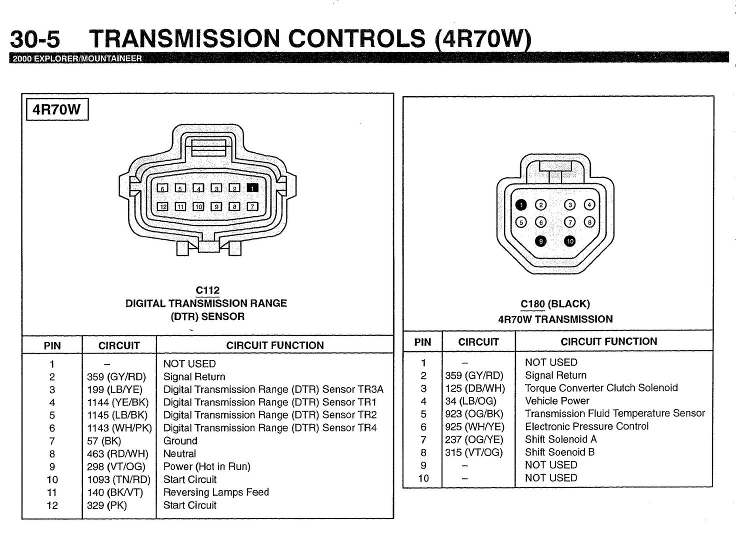
7. Shift Solenoid B...............................................Shift Solenoid B................................(C180 pin #8)
8. Shift Solenoid A...............................................Shift Solenoid A................................(C180 pin #7)
9. Torque Converter Control....................................Torque Converter Clutch Solenoid.......... (C180 pin #3)
10. Line Pressure Ctrl Solenoid.................................Electronic Pressure Ctrl...................... (C180 pin #6)
11. Selector Input B............................................. DTR tr2......................................... (C112 pin #5)
12. Selector Input A............................................. DTR tr1......................................... (C112 pin #4)
13. serial RX......................................................N/A
14. serial TX......................................................N/A
15. Bootloader....................................................
16. Shift Solenoid D............................................. N/A
17. Shift Solenoid C............................................. N/A
18. Sensor Ground...............................................sensor grounds (fluid temp, output shaft speed etc.)
19. Serial connector Ground...................................N/A
20. Sensor Ground...............................................sensor grounds (fluid temp, output shaft speed etc.)
21. Engine Input Shaft Speed (- VR2).........................
22. Power Ground...............................................battery negative terminal
23. Power Ground...............................................battery negative terminal
24. Spare Analog Input.........................................
25. Coolant Temp Sensor...................................... N/A
26. Trans Temp Sensor.........................................Transmission Fluid Temp Sensor............... (C180 pin #5)
27. TPS.......................................................... N/A
28. 5v Ref Output.............................................. N/A
29. Selector Input C............................................ DTR tr3a .........................................(C112 pin #3)
32. Output Shaft Speed Sensor (+ VR1)...................... OSS sensor signal to PCM (speedo plug blue wire w/yellow stripe)
33. Output Shaft Speed Sensor (- VR1)......................
34. Selector Input D............................................ DTR tr4............................................ (C112 pin #6)
35. Speedometer Output.......................................(connect to speedo in vehicle)
question #1
i have a OSS, the way it is wired according to my EVTM is "Signal" wire to PCM and a "Signal Return wire" that looks
like it gets spliced into every other signal return wire on the truck lol... Do i use the wires from the OSS as one of the input or output speed sensors and if so,
what wires are positive and negative?
* answer, Signal wire goes to Pin 32, and Signal return goes to sensor ground * as per DIY autotune tech support
question #2
Sensor Ground, Power Ground, Signal Ground... should i tie any of these into my microsquirt engine controller or a ground strap to the transmission? the
transmission DTR (Digital Transmission Range sensor) plug has a ground wire on the evtm but mine is actually blank and never had a pin. Should i use the
"signal ground" wire for all the "signal return" wires from the transmission? the sensor ground wires i dont think i need because im getting all the info from the CAN bus right?
*answer, in this setup Signal grounds go to the transmission sensors, fluid temp and speed output shaft. power ground goes to battery. serial ground is one of the 3 wires for the interface port * as per DIY autotune tech support
question #3
coolant temp and tps should be coming over from the CAN buss wires, but shouldnt these be twisted and shielded? and the 5v ref wire, i probably dont need
that because tps is coming over from CAN buss right?
*answer, can bus wires dont need to be twisted (they are already very noise resistant) but it does help. this setup doesnt require the 5v reff to be connected. * as per DIY autotune tech support
i have a 2001 toyota tacoma that i swapped this into, 5.0 supercharged gt40 explorer motor with 4R70W transmission and manual transfer case. im sorry if this seems like a lot to ask, im reading and i dont see a lot of people doing this so i dont have a lot to go off of. id like to know what some of these other wires go to, and i have a few questions at the bottom.
On my 2000 Ford 4R70W transmission this is what i have so far and or have assumed correct:
1. 12v Switched Power.........................................(12v key on power, splice in from other microsquirt ms3 engine controller)
2. CAN High.....................................................(connect to CAN High on other ms3 engine controller)
3. CAN Low......................................................(connect to CAN Low on other ms3 engine controller)
4. Engine Input Shaft Speed (+ VR2)..........................
5. Spare Analog Imput..........................................
6. Brake Switch Imput..........................................(brake pedal switch {GROUND not positive})
7. Shift Solenoid B...............................................Shift Solenoid B................................(C180 pin #8)
8. Shift Solenoid A...............................................Shift Solenoid A................................(C180 pin #7)
9. Torque Converter Control....................................Torque Converter Clutch Solenoid.......... (C180 pin #3)
10. Line Pressure Ctrl Solenoid.................................Electronic Pressure Ctrl...................... (C180 pin #6)
11. Selector Input B............................................. DTR tr2......................................... (C112 pin #5)
12. Selector Input A............................................. DTR tr1......................................... (C112 pin #4)
13. serial RX......................................................N/A
14. serial TX......................................................N/A
15. Bootloader....................................................
16. Shift Solenoid D............................................. N/A
17. Shift Solenoid C............................................. N/A
18. Sensor Ground...............................................sensor grounds (fluid temp, output shaft speed etc.)
19. Serial connector Ground...................................N/A
20. Sensor Ground...............................................sensor grounds (fluid temp, output shaft speed etc.)
21. Engine Input Shaft Speed (- VR2).........................
22. Power Ground...............................................battery negative terminal
23. Power Ground...............................................battery negative terminal
24. Spare Analog Input.........................................
25. Coolant Temp Sensor...................................... N/A
26. Trans Temp Sensor.........................................Transmission Fluid Temp Sensor............... (C180 pin #5)
27. TPS.......................................................... N/A
28. 5v Ref Output.............................................. N/A
29. Selector Input C............................................ DTR tr3a .........................................(C112 pin #3)
32. Output Shaft Speed Sensor (+ VR1)...................... OSS sensor signal to PCM (speedo plug blue wire w/yellow stripe)
33. Output Shaft Speed Sensor (- VR1)......................
34. Selector Input D............................................ DTR tr4............................................ (C112 pin #6)
35. Speedometer Output.......................................(connect to speedo in vehicle)
question #1
i have a OSS, the way it is wired according to my EVTM is "Signal" wire to PCM and a "Signal Return wire" that looks
like it gets spliced into every other signal return wire on the truck lol... Do i use the wires from the OSS as one of the input or output speed sensors and if so,
what wires are positive and negative?
* answer, Signal wire goes to Pin 32, and Signal return goes to sensor ground * as per DIY autotune tech support
question #2
Sensor Ground, Power Ground, Signal Ground... should i tie any of these into my microsquirt engine controller or a ground strap to the transmission? the
transmission DTR (Digital Transmission Range sensor) plug has a ground wire on the evtm but mine is actually blank and never had a pin. Should i use the
"signal ground" wire for all the "signal return" wires from the transmission? the sensor ground wires i dont think i need because im getting all the info from the CAN bus right?
*answer, in this setup Signal grounds go to the transmission sensors, fluid temp and speed output shaft. power ground goes to battery. serial ground is one of the 3 wires for the interface port * as per DIY autotune tech support
question #3
coolant temp and tps should be coming over from the CAN buss wires, but shouldnt these be twisted and shielded? and the 5v ref wire, i probably dont need
that because tps is coming over from CAN buss right?
*answer, can bus wires dont need to be twisted (they are already very noise resistant) but it does help. this setup doesnt require the 5v reff to be connected. * as per DIY autotune tech support