PSIG wrote:..... Could you include the cam VR sensor on the Escort wheel when you test? I have a couple I could use in that combination...
Thanks again!

David
David,
We weren’t aware that the EDIS-4 equipped Escorts in the US used a cam sensor. Tell us more and I’m sure we can include it on our “NEED TO TEST:” list…
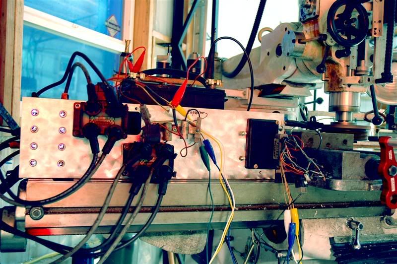
Ok, I was able to finish the test bench today, no thanks to Ron buying me a 5th of Bacardi as incentive to HURRY UP!!! . The Bench is made from a large chunk of aluminum channel with all the appropriate holes drilled and tapped into it for mounting modules, spark plugs, and various coil packs. It is designed for a variety of quick and easy bolt up configs in very short order. On the right end of the bench is where the EDIS module goes, as far away as I could mount it away from the plugs and coils. On the left side are 8 spark plugs with the ground electrodes cut WAY back for much better visual “inspection” of the sparking event, thanks to Ron. I slotted the “channel” in such away that an EDIS-4 coil pack, or an EDIS- 6 can be mounted readily. I even went so far as slotting it for BOTH EDIS-8 coil packs as well. Then I made provisions for attaching the Dodge Neon 4 cylinder and Chrysler 6 cylinder coil packs as well. An all around EDIS 4, 6, and 8 testing facility. I think I covered at least 75% of the applications we might be testing in the future. At that, there is still room for the addition of other coils if the need arises.
First test on the new official test bench was my EDIS-6 system for my SOLO-II Datsun 240-Z using the Ford coil pack. Immediate sparks right from the get go, WOO-HOO. We had only one glitch that we still don’t know the answer to. When we shut down our prelim spin up that went perfectly, we set up the camera and went to restart it and no sparks. Hmmmm… . Did we somehow “POP” the EDIS-6 module?! After several attempts, nothing. We checked, double checked, and triple checked all the connections, every thing looked good. Tried spinning the 36-1, and again, nothing. After disconnecting the ground for a period of time and reconnecting it, turned on the mill and WA LA… SPARKS!!!!! No other issues arose during the rest of our initial play time with EDIS-6. (bizarre)
We stood in awe for awhile watching those 6 plugs sparking away while the mill run at 1480 RPM, the RPM’s confirmed with my ancient Cornwell “dial back to zero” timing light with built in tach which also has a setting for 2 stroke/wasted spark ign. It is old and slow, but it works, and seems to work fine.
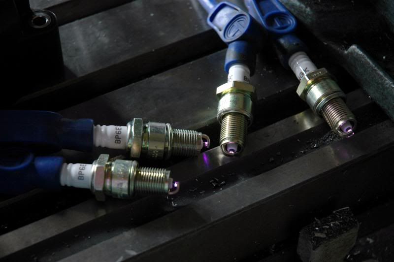
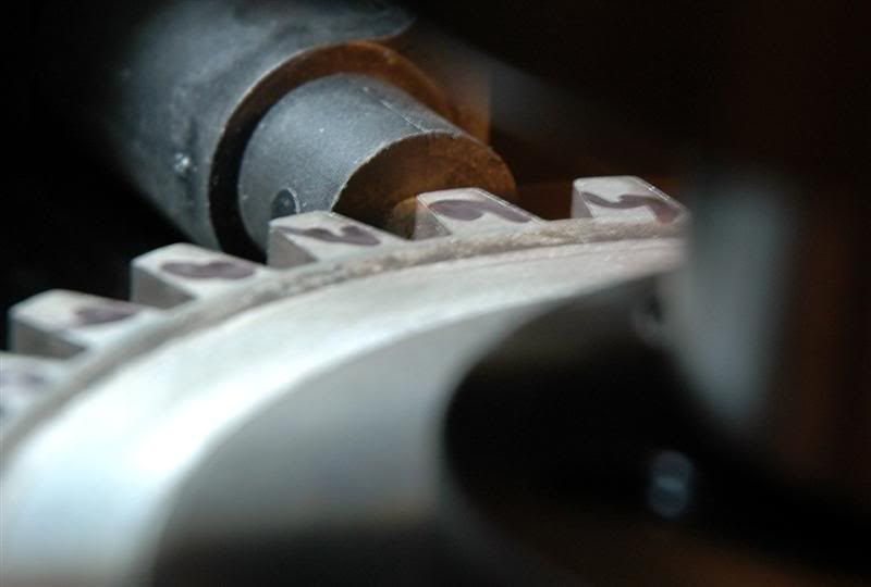
I marked the 36-1 wheel with a sharpie and verified that the EDIS-6 does spark, off of the 6 tooth back from the missing tooth when set up properly. We expected the spark to be triggered at the “middle” of the 6th tooth, but in reality it was firing at the trailing edge of the 6 tooth (with the timing light set at 10 degrees BTDC. With the timing light set on zero, it was triggering off of the trailing edge of the 5th tooth behind the missing tooth as expected). I tired to get an accurate picture of this, but the angle only partial shows what I’m talking about. You can make out half the metal core of the VR sensor in that particular pic, and yes, that pic was taken with 36-1 “spinning” at speed and the timing light strobe visually stopped the 36-1 as it came around in the picture.
I know I’m forgetting something else but I’m sure Ron will fill-in whatever I missed, right Ron?
Overall, it was pretty neat to watch those “spark bolts” all lit up. Depending on our schedules over the next few weeks, we hope to do more testing, though no guarantees. I have a customers cylinder head that takes precedence over ALL other projects when it arrives…
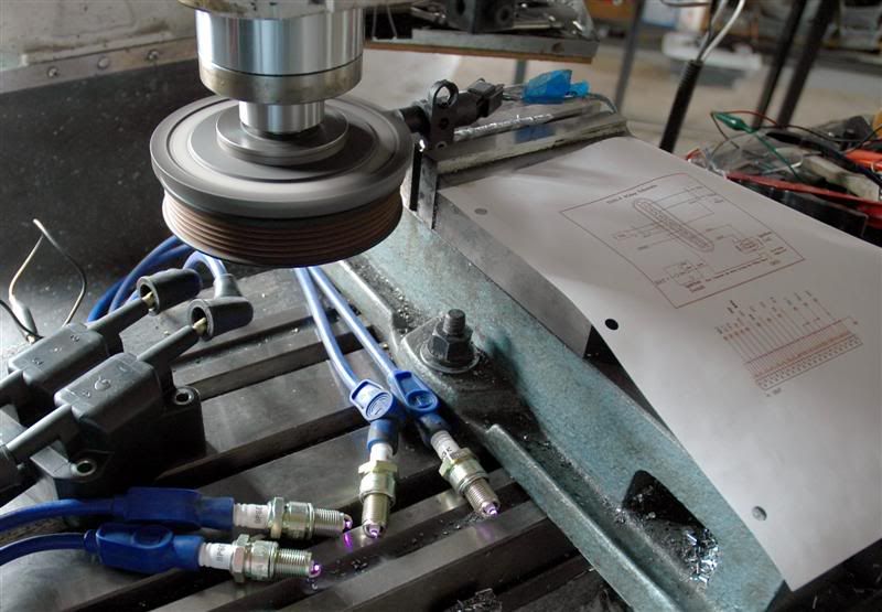
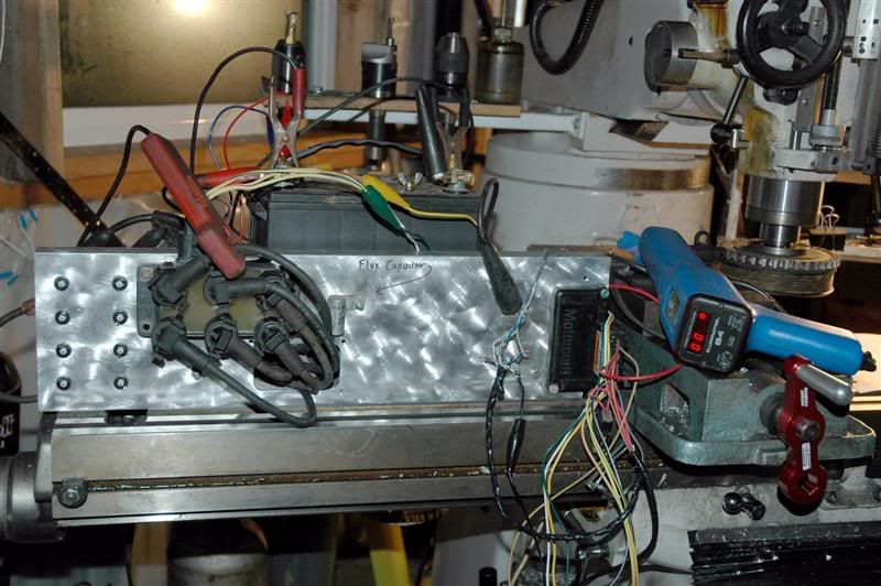
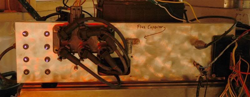
The pic below is the test bench all ready to go. Left to righ:…, Spark plugs, EDIS coil pack next to that, EDIS-6 module, then the DBtoZ timing light, and the 36-1 wheel in the quill. Behind the whole apparatus is the automotive battery for power.
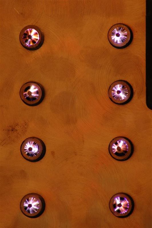
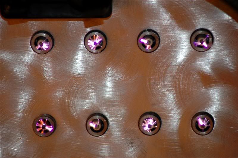
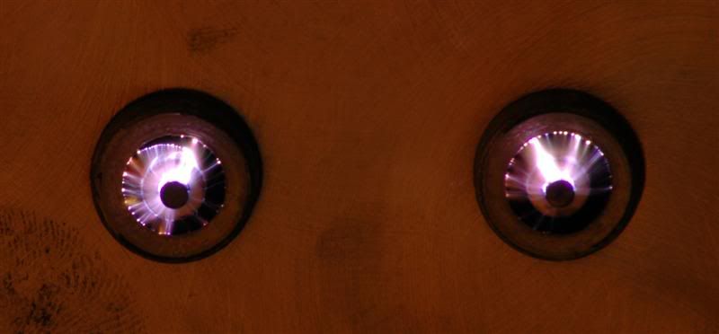
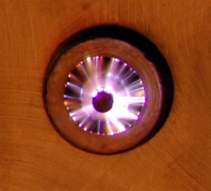
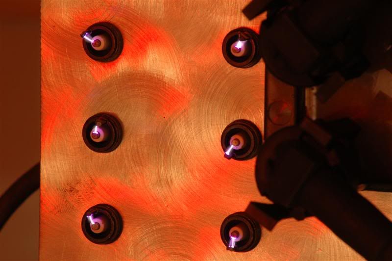
The pic below shows 6 plugs all lit-up from the running EDIS-6 system, WOO-HOOO... (note the "flux capacitor", LOL)....
This was our best shot of the plugs doing their job. This was a 15 second exposure and I think the 36-1 was spinning at 3400 RPM or there abouts. Ron would remember the exact RPM. At any rate, hundreds if not thousands of sparks are captured in this one picture.
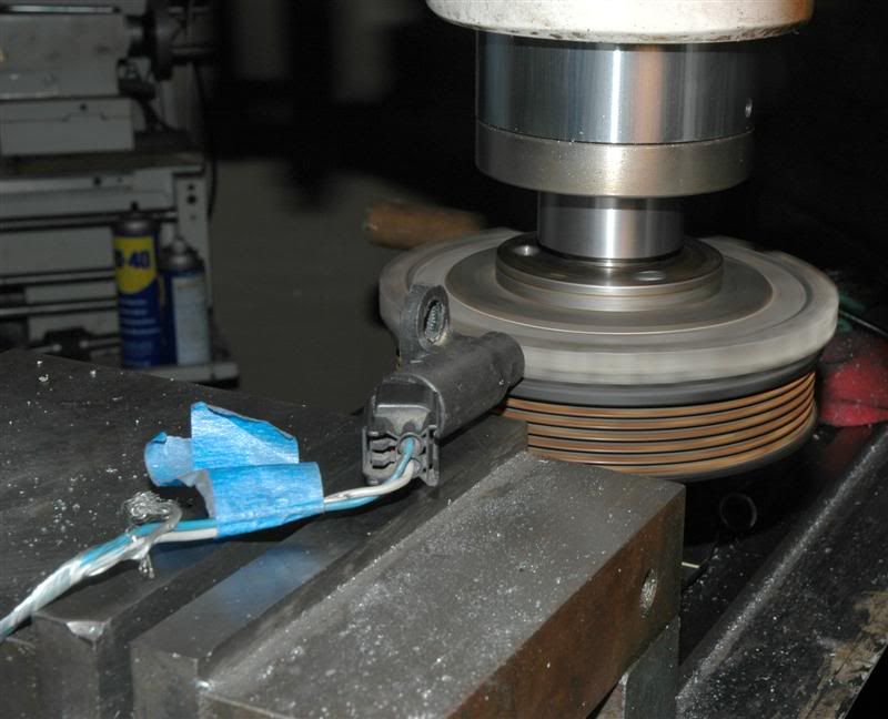
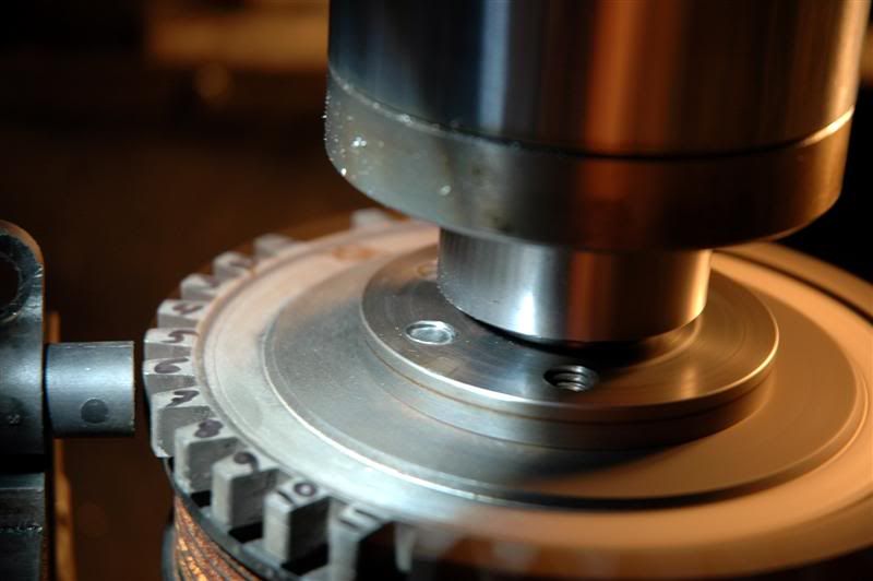
This picture shows the 36-1 wheel spinning, (right hand side of the wheel is a blur from the extended exposure time), while the strobe of the timing light optically stopped the wheel on the left hand side. If you look closely, you can make out the missing tooth just to the left of the quill.
The pic below is of the 36-1 spinning under the strobe of the DBtoZ timing light and the camera was able to capture exactly what we saw. Note that the spark was actually occurring at the trailing edge of the 6th tooth. We were under the impression it fired in the middle of that tooth.
Till the next update….…..