Ok so here is my dilemma I have spent several months trying to figure out what the hell is wrong with my silver top. I have set it all up and it BARELY runs. Cylinder one is firing all strange, it barely fires at all and the other cylinders pause sporadically.
Here are all the specs.
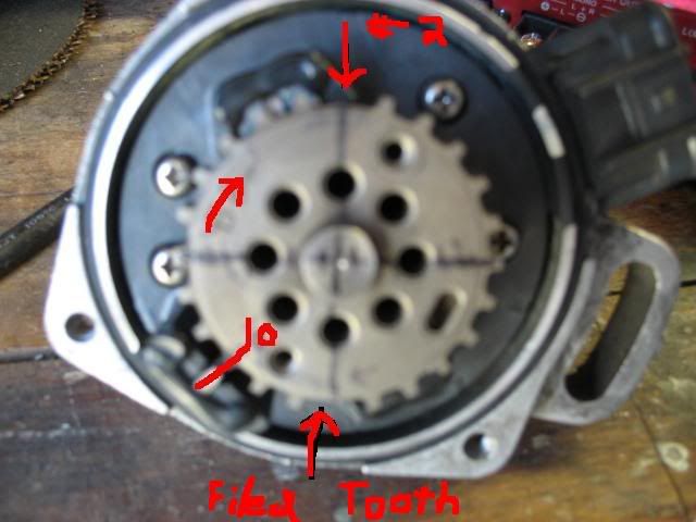
I have aligned it 10 deg BTDC and I counted three teeth back and filled off one of the teeth. Then I filed the one off that was directly across from it as seen in the picture.
My MSnS-E settings are:
Trig Pos A 1
Trig Return Pos A 3
Trig Pos B 7
Trig Return Pos B 9
With a trigger angle of 70 deg
I also have selected Generic Wheel Decoder and have the output on Spark A or the First LED, I have included 330 ohm from R26 to IGBTIN and I have jumped out R43 and removed R57. Also jumped IGBTOUT to IGN
Are you using a distributor ? I can't quite see in the video.
Cause the trigger set up is for a two coil wasted spark setup.
I have just got a blacktop running with that trigger setup, two coil wasted spark and two vb921's.
Position A is the vb921/coil connected to plugs 1&4
Position B is the vb921/coil connected to plugs 2&3
Not sure how you would setup up a distributor with the toyota triggers.
Just so I understand..... do you have the distributor cap and rotor? How many vb921 are you using?
If I understand correctly you are using one vb921 (spark A/position A) and a distibutor cap and rotor button. When position B is on the wheel triggers the MS there is no sparkB output configured so the distributor is only firing on 1&4.
I dont see how you can use that wheel setup with a distributor cap and rotor.
Get a second vb921 connect it to LED 19/D16 and a set of wasted spark coils.
1) Are the VR sensor leads wired correctly... did you get Ne+ and the shared ground backwards?
2) Do you have the dwell set high enough? If it's misfiring it could just be that you don't have enough dwell.
I'm running pretty much the exact same setup you are, only I'm using rx7 leading coilpacks for wasted-spark ignition. I checked your distributor pic against mine, and it looks to me like you're doing the exact same thing I am for which teeth you cut.
So to answer all of your questions I am using everything stock except for the modifications to the distributor, where I have filed off two of the teeth, which muythaibxr said looks like his so I am now almost 99% sure it is not the problem. I have G- (Red Wire) as/to Ground and NE (Black) as my trigger or pin 24
The wires are all twisted together and are in shielding (the main harness is a special wire which has 24 wires in it shielded in pairs of two and have a blank wire to filter noise) except for the parts that come out of the main harness.
What I will try to do tonight is grounding out G1 and G2 and I would like to shield the wires. BTW how do you shield wires beside twisting them together and running a blank un-shielded wire around them to ground?
I WOULD ALSO LIKE TO GET YOUR DWELL SETTINGS JUST TO SEE WHERE I AM AT THANX =)
LAST NOTE:
I WAS ABLE TO GET IT RUNNING ALMOST WELL WHEN I PUT IT ON A TRIGGER ANGLE OF 30 deg. I will get a video and post it. The only thing is the tach was jumping all over the place and it would not idle or go above 4000rpm
The sound of engine is like the other engine that I have heard with the spark plug leads mixed up.
Did you have the engine running before fitting MS?
If it were me I would go back to basics and work throught the timing. I had to do this to get my engine running and found that I had the coil packs wired the wrong way around and the engine sounded similar to yours. Never trust anything until you had tested it and proven the results. If you don't get the results you expect stop and work out why.
With the engine set to 10 degrees before tdc on the firing stroke of no 1 is the rotor button pointing to the tower for no1?
Remove the spark plugs to reduce the load on the starter. Put a plug in number one lead and ensure the plug is laying on grounded metal. Connect your timing light to the number one lead, set MS to a fixed angle of 10 degrees. Crank the engine, adjust the distributor to 10 degrees if this can't done within the normal adjustment of the distributor try to determine how far out the adjustment is record this value as this will help you determine where the problem lies.
Fit new plugs as they are cheap and it is worth the piece of mind. Refit your plug leads on at a time checking that the firing order is 1-3-4-2 remember the distributor rotates anti clockwise. Leave the timing light in place.
Try to start the engine, watch the timing light, does it flash at the correct time. Try to start the engine with the fixed spark angle and without it set. Remember to set it to -10 when you are done.
Thats probably enough for one post, let us know what the results are.
gon wrote:I am in the process of cutting 2 tooth's out of a 24 tooth distributor wheel, and I don't agree with the tooth's that you have cutted, I think that you have cutted the tooth's at 90 ATDC and not BTDC.
Can someone confirm or not ( using the first post picture) ?
In the picture the engine is at top dead center. right ?
No, he cut the right teeth, 100 deg BTDC if the engine is at 10 btdc.
He cut the same teeth I did, and my timing is dead-on in the car using wheel settings of 1,3 7,9 and an angle of 70 btdc.
AGAIN, looking at the picture that he posted, it looks like he cut the exact same teeth I did, and I KNOW my setup is correct, as its working great in a running engine:
I did this by putting the distributor in the engine, and setting the engine to 10 deg btdc. Then I aligned the distributor so the Ne sensor lined up with a tooth, and counted back in the opposite direction of the engines rotation 3 teeth, and cut the one that ended up being 100 deg BTDC, and the one exactly opposite on the wheel.
However, I'm not sure if the Red wire is the G- wire... I'll have to look at my car when I get home, but I could've sworn I was using a black wire and a white wire from the original harness.
