https://github.com/kckr for some of the basic code. Apologies, just realized I never actually pointed a link to the code. The main gauge code (Squirtview) is.. pretty ugly. I'm starting to wrap my head around object oriented a bit better, so I've made lots of changes - but it all needs a refactor.
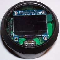
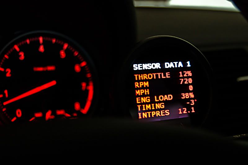
In the meantime - I 3D printed up a bezel and put the gauge inside the gauge cluster of my miata and made a simple demo mode.

https://www.youtube.com/watch?v=PyqZvAkLr4k
Running into some problems with the LC1 - or least, something that explains why my XD16 gauge stopped working correctly. Air/Fuel Ratio = ((lambda) + 500)* (stoich) / 10000 - for some reason my benchtop LC1 thinks that's 4.9 instead of 14.7. Easy enough to code around, but won't fix my XD16 (unless I start playing man in the middle). It is sorta fun burning pieces of paper to lower the oxygen content of a jelly jar to verify it's working - plus piece of mind knowing it's not sending bogus values to MS before I enable it on my car. I'll have to try reflashing once I find my cable/remember who I lent it to.
