After measuring the resistance of the pins and finding them not to be like a stepper motor at all I pulled the actuator apart. It has a decent amount of electronics packed inside as well as a hall sensor. It appears to be a stepper motor with a bunch of drive circuitry. To use this board it would have to be stripped away. I'm going to look into what kind of signal the ECU uses to interface with the actuator. Who knows if they will want to share it.Joe Clark wrote:I too would be very interested in the ability to use this to control boost on a VGT turbo.
aero wrote:I'm very interested in trying to use this project to control a Holset VGT turbo with its stepper motor control for boost control.
How is it coming?
BETA :) RELEASE of PWM 2 STEPPER controller
Moderators: jsmcortina, muythaibxr
Re: BETA :) RELEASE of PWM 2 STEPPER controller
Enrico, do you still working on the board?
I've re-arranged the code a little bit to compact it into 1K-word, so it could be compiled with free PICC-Lite compiler for a pic16f627a profile, and also added support for opensource (free) SDCC compiler. But, I see the code uses external oscilator in its CONFIG register and its probably not the latest and the greatest code available.
In case you're still intersted in design with internall oscillator and ICSP, I would be glad to submit my changes to you for inclusion in next release.
-
TurboCamaro
- Experienced MS/Extra'er
- Posts: 255
- Joined: Mon May 24, 2004 8:07 am
- Location: TX
- Contact:
Re: BETA :) RELEASE of PWM 2 STEPPER controller
Have you had a chance to get the gerber file(s) together for the last stable board?
-Wayne
1994 3.4L V6 Camaro 5 spd.
Custom Turbocharged/Intercooled
1994 3.4L V6 Camaro 5 spd.
Custom Turbocharged/Intercooled
Re: BETA :) RELEASE of PWM 2 STEPPER controller
No, I don't.
I hope masterx81 will release the Eagle .BRD file sooner or later.
I hope masterx81 will release the Eagle .BRD file sooner or later.
Re: BETA :) RELEASE of PWM 2 STEPPER controller
Any news on that? Is there anyone working at project? What is the actual status?
Chevrolet Corsa Wind 1.0 EFI (not squirted yet)
someday a Chevrolet/Opel Corsa 20XE 2.0 16v Turbo Squirted o_0
(Assembling V3-I and V2.2)
someday a Chevrolet/Opel Corsa 20XE 2.0 16v Turbo Squirted o_0
(Assembling V3-I and V2.2)
Re: BETA :) RELEASE of PWM 2 STEPPER controller
Hi!
Sorry for my absence...
I've seen that arkadi has the knowledge to manipulate the code...
This is a good thing, as i haven't any spare time to dedicate to this project...
It's interesting the SDCC thing... When i've started the project that compiler wasn't fully working on that chip, so i've opt for the hi tech...
Have you done some code optimization? Probably ont he iterpolation function we can do a better job... the cpu take a lot to do that math! Probably we can try to not use floating point variables...
As now, i'm always in a stop state, with the board nearly completed for the serial communication, but the code need to be modified...
One of this evenings i try to send you all the material... If you can help me, probably we can go futher on this project..
But, as now, someone has already used succesfully this adapter in a real-world application?
I need at least some feedback before put on it other time...
I suppose that the stepper it's a lot slow compared to pwm, and apart bench simulations, i haven't never tested it in a car...
Enrico
Opel/Vauxhall Corsa GSi MS2
Subaru v4 EJ20 MS3
Opel/Vauxhall Corsa GSi MS2
Subaru v4 EJ20 MS3
Re: BETA :) RELEASE of PWM 2 STEPPER controller
The SDCC generates considerably larger (2x) code compared to PICC. This is largely due to extensive use of BANKSEL instruction. But it fits into 2k.
I haven't verified the result, because I don't have a working board yet, because I opted to go with already assembled PIC core - the Olimex PIC-PG4 (EUR 20) development board and programmer with a plan to add stepper driver manually. The code is not a problem for me, but electronics and availability of free time is.
I don't think the performance is a big issue here - at 20MHz the PIC is pushing 5MIPS (1MIPS in your design or on internal 4MHz oscillator). Yet by converting interpolation function into macro the compiler is able to cut the number of required instructions considerably.
LinearInterpolate() arguments are all constants, except CurrDC and maybe MaxUsableSteps, so the expression:
where:
reduces to:
More optimizations are possible in other parts of the code.
I haven't verified the result, because I don't have a working board yet, because I opted to go with already assembled PIC core - the Olimex PIC-PG4 (EUR 20) development board and programmer with a plan to add stepper driver manually. The code is not a problem for me, but electronics and availability of free time is.
I don't think the performance is a big issue here - at 20MHz the PIC is pushing 5MIPS (1MIPS in your design or on internal 4MHz oscillator). Yet by converting interpolation function into macro the compiler is able to cut the number of required instructions considerably.
LinearInterpolate() arguments are all constants, except CurrDC and maybe MaxUsableSteps, so the expression:
Code: Select all
LinearInterpolate(0,0,100,MaxUsableSteps,CurrDC)
Code: Select all
int LinearInterpolate(char X1,char Y1,char X2,char Y2,char XX) {
	return ((XX - X1) * (Y2 - Y1) + Y1 * (X2 - X1)) / (X2 - X1);
}
Code: Select all
((CurrDC - 0) * (MaxUsableSteps - 0) + 0 * (100 - 0)) / (100 - 0)
=
(CurrDC/100)*MaxUsableSteps
Re: BETA :) RELEASE of PWM 2 STEPPER controller
whooo, you are right
This will lighten the code by a lot
Probably can be optimized another little avoiding float point variables...
This will lighten the code by a lot
Probably can be optimized another little avoiding float point variables...
-
Mad Professor
- Experienced MS/Extra'er
- Posts: 362
- Joined: Mon Jun 06, 2005 7:52 am
- Location: UK
- Contact:
Re: BETA :) RELEASE of PWM 2 STEPPER controller
I have just been pointed to this post, as I am unable to control the 5-Wire Unipolar Idle Control Valve in my mini or my metro.
Both my Mini & Metro used to run on the Rover MEMs ECU, both of the idle control valves use the same plus, and wires.
The Metro's idle control valve is mounted on the inlet manifold and uses a by-pass port.
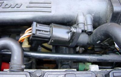
The Mini's idle control valve is apart of the SPi Throttle Body, which actuates the throttle plate.
I have read from page 1 and can't see anyone here using this for use with a Unipolar Idle Control Valve.
Can you please tell me if this is able to drive my Unipolar idle control valves.
Thanks for your time.
Both my Mini & Metro used to run on the Rover MEMs ECU, both of the idle control valves use the same plus, and wires.
The Metro's idle control valve is mounted on the inlet manifold and uses a by-pass port.
The Mini's idle control valve is apart of the SPi Throttle Body, which actuates the throttle plate.
I have read from page 1 and can't see anyone here using this for use with a Unipolar Idle Control Valve.
Can you please tell me if this is able to drive my Unipolar idle control valves.
Thanks for your time.
Re: BETA :) RELEASE of PWM 2 STEPPER controller
hi Mad Professor,
i am in the same situation like you. and develloped together with some friends there will be soon a controler made especially to control the Rover steppers (possible to make it work with other unipolar steppers).
as far as i know this controller here is made for bipolar steppers. i tried it and modified the Rover motors (from unipolar to bipolar) but couldn't made it work
Rover Mini, 1275ccm, TBi
MS1, V2.2 Board, 29y4Code
MS1, V2.2 Board, 29y4Code
-
DaveW
- Experienced MS/Extra'er
- Posts: 151
- Joined: Mon May 17, 2004 9:05 am
- Location: North Yorkshire, UK
- Contact:
Re: BETA :) RELEASE of PWM 2 STEPPER controller
The driver chip in this circuit won't drive a unipolar stepper.
Using the same principle of operation and substituting the bipolar driver for a unipolar one would be possible. Using a UCN5804B, for example, would drive your IAC with some minor changes to the code and hardware design. If anything the code would be simpler as this IC uses 2 simple inputs, direction and step so doesn't have to worry about phase outputs.
Another option might be to replace the unipolar with a bipolar. They'd have to be compared more closely but the 4 wire bipolar used on the Rover 4.6 (GEMS) and the GM LS engines looks to be a very similar size and fitting to the one on your vehicle and MIGHT be a straight swap in which case you could use the design as is.
MobiSquirt - iPhone app for Megasquirt and Megajolt
It Runs !!! 3.9 V8 MSnS Extra
http://www.msruns.com/viewtopic.php?t=5106
5.7 Corvette V8 MSnS Extra
http://www.msruns.com/viewtopic.php?t=20094
It Runs !!! 3.9 V8 MSnS Extra
http://www.msruns.com/viewtopic.php?t=5106
5.7 Corvette V8 MSnS Extra
http://www.msruns.com/viewtopic.php?t=20094
-
Mad Professor
- Experienced MS/Extra'er
- Posts: 362
- Joined: Mon Jun 06, 2005 7:52 am
- Location: UK
- Contact:
Re: BETA :) RELEASE of PWM 2 STEPPER controller
Befor I came across this topic I was looking at building a simple circuit using a Picaxe 18X Microcontroller (PIC16F88-I/P) to read the PWM singal and to give outputs to a L293D Push-Pull Four Channel Driver With Diodes, to control the Unipolar Stepper.
The L293D is also more the able to control unipolar & bipolar stepper motors.
The L293D is also more the able to control unipolar & bipolar stepper motors.
Last edited by Mad Professor on Wed Aug 13, 2008 7:54 am, edited 2 times in total.
-
DaveW
- Experienced MS/Extra'er
- Posts: 151
- Joined: Mon May 17, 2004 9:05 am
- Location: North Yorkshire, UK
- Contact:
Re: BETA :) RELEASE of PWM 2 STEPPER controller
Creating a version of this board using an L293D would certainly be an option and maybe add a jumper to select unipolar or bipolar output to save having 2 versions of the code. I can't think of any reason why the board wouldn't then be able to control unipolar or bipolar IACs with the same hardware design.
I was going to do a cost comparison with a UCN5804B and found it doesn't seem to be available any more so is probably not an option anyway.
I was going to do a cost comparison with a UCN5804B and found it doesn't seem to be available any more so is probably not an option anyway.
MobiSquirt - iPhone app for Megasquirt and Megajolt
It Runs !!! 3.9 V8 MSnS Extra
http://www.msruns.com/viewtopic.php?t=5106
5.7 Corvette V8 MSnS Extra
http://www.msruns.com/viewtopic.php?t=20094
It Runs !!! 3.9 V8 MSnS Extra
http://www.msruns.com/viewtopic.php?t=5106
5.7 Corvette V8 MSnS Extra
http://www.msruns.com/viewtopic.php?t=20094
Re: BETA :) RELEASE of PWM 2 STEPPER controller
I know that this topic still. Economies have doubts and need help from you.
Maybe I am writing so strange. And I'm using "google translator."
My main doubt is the connection scheme that plaque.
I came to build it so that you do not know how to install it.
I would like to thank everyone.
Maybe I am writing so strange. And I'm using "google translator."
My main doubt is the connection scheme that plaque.
I came to build it so that you do not know how to install it.
I would like to thank everyone.
-
ptegler
- Experienced MS/Extra'er
- Posts: 150
- Joined: Tue Nov 09, 2004 9:32 pm
- Location: Severn, MD
- Contact:
Re: BETA :) RELEASE of PWM 2 STEPPER controller
I built this borad up about 3 months ago (or more) and have it hooked up to the MS box on the bench behind me here. I have it all working...but for the life of me can not now find the instructions I remember reading on how the switches work. Does anyone have a link to the blurb that in straight forward terms describes the operational procedures for setup and switch use.
thanks
ptegler
thanks
ptegler
ptegler
ptegler @ cablespeed.com
My Success story: http://www.msruns.com/viewtopic.php?t=21806
Home site: http://www.teglerizer.com/Injected_Spit6.htm
ptegler @ cablespeed.com
My Success story: http://www.msruns.com/viewtopic.php?t=21806
Home site: http://www.teglerizer.com/Injected_Spit6.htm
Re:
This would be?
masterx81 wrote:
New Release! Ver. 1.2
New schematic and new code...
Remain to do a decent documentation...
In the zip there is:
- main.c file. This is the c source code (compiled with HI-TECH PICC compiler). It's very well commented. If you modify this, please leave my name in
- PWM2STEPPER.hex. Precompiled hex file for the pic 16f628. This is preconfigured with (possible) reasonable values for gm stepper (Step Time 3.0ms, Step count 170, 100 usable steps for conversion, moving only, 1% threshold in pwm change before taking in account a stepper moviment, load line ENABLED, for 1 sec, increase the idle by 30 steps)
- Schematic.bmp. Schematic circuit... It's not that nice, but if you not understand it, probably is better that you leave this project for now...
- Board.bmp. Board for wo want to build the pcb.
- Components.bmp. The values of the various components.
- A ICProg Shot for configuring different default values.
If you need different values that de preconfigured, you need to modify the eeprom values before programming the pic:
- The address 0000 configure the max steps that your stepper can do (0 - 255).
- The address 0001 is the step time (in 0,1ms - so 30 = 3.0ms) (0 - 255)
- The address 0002, if set to 0, energizes the coil of the stepper only gor the moviment. If set to 1, configure the the power will remain at the stepper always. If set to 2, leave always power the first 15mins, after that, switch to moving only. (0 - 1 - 2).
- The address 0003 is the threshold
- The address 0004 is the delay (in ms) that the stepper wait before move, when you are in manual mode (smaller times gives low resolution, but fastest moviment; higher permit fine changes of the idle, but slowest moviment)
- The address 0005 is the useful steps that i take in care doing the calcs.
This is here because the pintle, also if not fully open, allow already to pass the flow. This can give at the stepper a smaller range, making it more fast. Remember that a stepper valve, compared to a PWM one, is very slow changing from fully open to fully closed (this wan an original idea of slow_hemi6) (0 - 255)
- The address 0006 is the number of steps to retract (increase idle) when there is a change from 0 to +5 (or +12 - this line is protected). If set to 0, the load line is disabled.
- The address 0007 is the time to leave the idle increased (in seconds)
How it work:
First of all, it EXTEND the pintle, for finding the 0 position.
Then it calculate the duty cycle of the pwm signal (with frequency from 50 to 200 hz - SET 255 VALUE FOR MSNS-E FRO BETTER RESULTS - 50Hz), then moves the stepper proportionally to the duty.
DC at 100% means stepper fully open, DC 0% means stepper fully closed.
For now, it made a linear interpolation, but if necessary i can made a little table.
There are 2 buttons. This are for manual controlling the stepper moviment.
Pressing them together, the led will go on, and you are ready for manual adjustment. Up button increase idle, Down decrease idle.
Pressing the together a second time, the stepper return in auto mode.
In this version there is the addition of the load line. If this line goes from low to high, the stepper will increase the idle of N steps for T time. Both are configurable. I've placed a jumper for selecting pull-up or pull down. Pin 1 is on the bottom. Jumpering 1 and 2, gives a pull-up, 2 and 3 gives a pull-down. If you don't need any pull-up or pull down, does not install this jumper.
From experiments made by me (on the bench), and by DaveW (on a real car), we are nearly sure to say that this converter WILL work, giving the ability to the great msns-e firmware to control a stepper idle motor.
Post here any comment/problem...
---
For the recent problems with the forum, i've uploaded the file on a free ftp server. The link is the following:
http://digilander.libero.it/Enrico.1981 ... 20v1.2.zip
-
Keithg
- Super MS/Extra'er
- Posts: 2413
- Joined: Sun Mar 06, 2005 9:15 am
- Location: Chicago, IL, USA
- Contact:
Re: BETA :) RELEASE of PWM 2 STEPPER controller
Actually, 255 in the freq box means 37.2 hz, not 50. In the re-write of CLidle in HiRes, I will make sure this mode is not clobbered.
KeithG
KeithG
-
twiganbone
- MS/Extra Newbie
- Posts: 1
- Joined: Wed Apr 08, 2009 3:09 am
Re: BETA :) RELEASE of PWM 2 STEPPER controller
hi ya all just been phoneing about trying 2 get sum 1 to make the pcb from the art work and carnt find ne 1 to do it .is thair ne 1 who would sell me 1 i am in essex. this is just what i need thanks andy
-
slyrye
- Experienced MS/Extra'er
- Posts: 255
- Joined: Sun Aug 12, 2007 2:41 pm
- Location: Philippines
- Contact:
Re: BETA :) RELEASE of PWM 2 STEPPER controller
Hi guys;
I'm wanting to know How much steps would the loadline would drive the stepper motor? is this configurable? or fixed permanently by default to a certain value?
I'm wanting to know How much steps would the loadline would drive the stepper motor? is this configurable? or fixed permanently by default to a certain value?
MSnS'n'4G15
-
DaveW
- Experienced MS/Extra'er
- Posts: 151
- Joined: Mon May 17, 2004 9:05 am
- Location: North Yorkshire, UK
- Contact:
Re: BETA :) RELEASE of PWM 2 STEPPER controller
All the settings, including the load settings, are configurable in the code but there is no configuration interface.slyrye wrote:Hi guys;
I'm wanting to know How much steps would the loadline would drive the stepper motor? is this configurable? or fixed permanently by default to a certain value?
MobiSquirt - iPhone app for Megasquirt and Megajolt
It Runs !!! 3.9 V8 MSnS Extra
http://www.msruns.com/viewtopic.php?t=5106
5.7 Corvette V8 MSnS Extra
http://www.msruns.com/viewtopic.php?t=20094
It Runs !!! 3.9 V8 MSnS Extra
http://www.msruns.com/viewtopic.php?t=5106
5.7 Corvette V8 MSnS Extra
http://www.msruns.com/viewtopic.php?t=20094