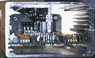
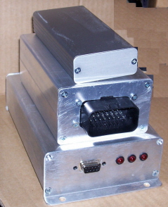
Peak and hold injector driver board

A forum for discussing the MegaSquirt related (but non-B&G) board development, assembly, installation, and testing.

Moderators: jsmcortina, muythaibxr

Post Reply
racingmini_mtl
Super MS/Extra'er
Posts: 9127
Joined: Sun May 02, 2004 6:51 am
Location: Quebec, Canada
Contact:

Post by racingmini_mtl »

After assembling and doing some testing, it is now obvious that the v2.0 board will not be an option for an 8-driver box. The packaging is already tight for a 4-driver box (but acceptable) but the main issue is heat management.

I have done some testing in a worst case setup with the 4-driver box. I used four 2 Ohm resistors instead of injectors. This puts the driver in current limiting (hold) mode almost instantly since the peak is reached very fast due to a very low inductance. This generates the most heat from the TIP122.

It appears that the small case is too small to effectively dissipate the heat generated. I did some tests at about 85-90% duty cycle and the case became too hot to handle comfortably after a few minutes. I then put the box on an empty relay board case and this made the situation better. It still wasn't enough but the contact was not optimum.

What I will do is get a 1/8" thick U-shaped aluminium bar and bolt it to the case using the transistor screws and heatsink grease. I think this will solve the issue. By the way, real world setups will be much less troublesome than my test setup. With a real setup, the peak period will be a significant percentage of the duty cycle and the peak mode generates much less heat in the transistors due to how they work. Also, most injectors have more impedance than the 2 Ohms I've used which will make quite a difference. Finally, most engines will not operate for extended periods at high duty cycles. I'll report back as soon as I have made the tests with the additional heatsink.

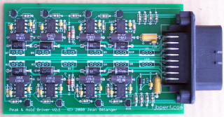
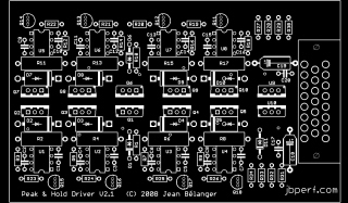
Since the v2.0 is not an option for more than 4 drivers, I have done another design which solves the packaging issue and should also solve the heat issue. Here is a picture of the planned board (click for a larger picture):
Image

The transistors will bolt to a 1/8" think T-shaped aluminium bar which will also bolt to the case. The board will be 3"x5" and will fit in the same case as the relay board (with both halves, of course) with the board in one half and the heatsink bolted to the other half. There is an on-board Ampseal connector with 23 contacts: 8 for the injectors, 8 for the injector control (to the ECU), 1 for 12V, 1 for low-current ground, and 5 for high current grounds. The larger mass of the case together with the large heatsink should be sufficient but there is always the possibility of using an external heatsink.

I'm getting parts to check the design and layout and I'll have the board made when I have checked everything fits as it should. The BOM will be the same as the 2-board v2.0 except for the case and the connector. Since the Ampseal connector can be a bit expensive it will be possible to do as for the v2.0 and use wire soldered directly to the board and external connectors.

I plan to have both the v2.0 and v2.1 available since they both have their application (assuming I can solve the heat issue). I may also provide heatsinks cut and drilled as needed but I'll have to see about that one.

Jean
jbperf.com Main site . . . . . . . . . . . . . . . . . . . . . . jbperf.com Forum
Image
JET
Helpful MS/Extra'er
Posts: 100
Joined: Tue May 04, 2004 7:02 am

Post by JET »

Any progress on the boards? cheers
racingmini_mtl
Super MS/Extra'er
Posts: 9127
Joined: Sun May 02, 2004 6:51 am
Location: Quebec, Canada
Contact:

Post by racingmini_mtl »

JET wrote:Any progress on the boards? cheers
I have the v2.1 boards (8-driver board) in hand and I have the components to assemble one, I just need to assemble it. I'll have time to do this and do some tests this weekend.

Also, the issue I mentioned about heat for the v2.0 (4-driver board) seems to be a false issue. The fact that the resistors do not have any significant inductance results in the LM1949 not being able to correctly regulate the current. This means that there is about 2 to 4 times as much heat being generated than there should normally be. I will be able to test with injectors instead of the resistors to confirm that there is no heat issue.

By the way, the BOM for the v2.1 board is available here.

Jean
Last edited by racingmini_mtl on Sun Sep 07, 2008 5:54 pm, edited 1 time in total.
jbperf.com Main site . . . . . . . . . . . . . . . . . . . . . . jbperf.com Forum
Image
myk777
Master MS/Extra'er
Posts: 510
Joined: Tue Mar 27, 2007 9:12 pm
Location: Bellevue, WA

Post by myk777 »

Maybe a dumb question, but the following statement is from the "overview" page for the P&H board:

Since the hi-res MS1/extra code can't do a PWM signal on the injectors, the only solution with the standard MS injector drivers is to either use hi-z injectors or use inline resistors. This board allows the use of low-z injectors without any resistors and without setting up any PWM parameter since the chip (LM1949) the board is based on takes care of setting the current correctly no matter what the battery voltage is or what injector is there. The LM1949 datasheet is available here.

It mentions that the injector current is automatically corrected for voltage changes, does this mean that we should use a battery voltage correction factor of 0.00 ms/V in megatune's engine constants page? Or am I way off base here, thanks.

Mike
racingmini_mtl
Super MS/Extra'er
Posts: 9127
Joined: Sun May 02, 2004 6:51 am
Location: Quebec, Canada
Contact:

Post by racingmini_mtl »

You still need to put the correct battery voltage correction factor because, even though the LM1949 will automatically correct the opening time, the MS will need to adjust the pulse width to compensate the battery voltage. If you put 0 then the pulse width will be shorter than it should in case of low voltage (or longer for higher voltage).

What is done automatically is the peak duration which means the injector will always open fully and as fats as possible.

Jean
jbperf.com Main site . . . . . . . . . . . . . . . . . . . . . . jbperf.com Forum
Image
myk777
Master MS/Extra'er
Posts: 510
Joined: Tue Mar 27, 2007 9:12 pm
Location: Bellevue, WA

Post by myk777 »

Thanks for the answer, is it fair to say that it probably affects the value then that goes into the correction factor or do you think it is completely independent as compared to the std MS-I arrangement? I guess I would need to hook my variable power supply up to the MS and see what affect this voltage has on the AFR at idle to set this up properly, or is there an easier way? Thanks.

Mike
racingmini_mtl
Super MS/Extra'er
Posts: 9127
Joined: Sun May 02, 2004 6:51 am
Location: Quebec, Canada
Contact:

Post by racingmini_mtl »

Unfortunately, I don't know of any method other than making measurements with different voltage values. But if you have a way of doing this (as you mention) then you can get a perfect correction factor.

Jean
jbperf.com Main site . . . . . . . . . . . . . . . . . . . . . . jbperf.com Forum
Image
RacerStev
MS/Extra Newbie
Posts: 23
Joined: Fri Jun 22, 2007 5:42 am

Post by RacerStev »

I'm running a MS2 with a V3 board and am experiancing a problem
that points to a bad injecter driver or a wrong setting on my part.

The problem is a lean condition at high rpm (over 5800-6000) or
at higher boost settings (19 to 20 psi). Pulse width makes no differance
in air/fuel when the above conditions are met.

I've logged fuel pressure and it's fine, duty cycle is only around 50%.
The injectors are 4 ohm, 1600cc.

My settings are

100%
25.6
and a PWM period of 66

Are these right or is there something else I can take a look at?

Update: I just ran the output test mode in the MS2, all is fine untill
about 10ms, 11sm sounds a little strange and at 12ms the injecotors
lockup.

I start to see the problem on the logs at about 10ms of fuel, so it seems
I found the problem. Just need to know how to repair the problem.

Steve
racingmini_mtl
Super MS/Extra'er
Posts: 9127
Joined: Sun May 02, 2004 6:51 am
Location: Quebec, Canada
Contact:

Post by racingmini_mtl »

If you have a stim, you can see if you get blinking injection LEDs. However, the best way to check if the drivers are functioning correctly would be with an oscilloscope connected to the injectors. There you would be able to see if you get the correct behaviour with the peak and hold phases.

The issue might be that you have 4 ohm injectors. First, are you sure that they are 4 ohms? If so, they can't be designed for a 4A/1A peak/hold setup with a 12V system. The P&H board has the components chosen to produce a 4A/1A peak/hold current with a 3.9ms maximum peak. Your injectors will never reach the 4A peak so they will always see a 3.9ms peak followed by a 1A hold current. This should work but might give more current than the injectors are designed for which might produce inconsistent results.

The LM1949 is designed to produce a 4-to-1 peak/hold current and the value is dependent on the sense resistor chosen. Most low-Z injectors have a value between 2 and 3 ohms and are designed for 4A/1A peak/hold current. If your injectors are designed for a 2A/0.5A then you would need to change the 0.1ohm sense resistors to 0.2ohm resistors. If they need an other peak/hold setup then you will need to chose the correct sense resistor value (as long as the peak/hold is in a ratio of 4-to-1).

Jean
jbperf.com Main site . . . . . . . . . . . . . . . . . . . . . . jbperf.com Forum
Image
jsmcortina
Site Admin
Posts: 39569
Joined: Mon May 03, 2004 1:34 am
Location: Birmingham, UK
Contact:

Post by jsmcortina »

When running in test mode, did you change the injection period?
The default is 12.8ms. So if you set the injection time to 12ms you'll be near 100%. Increase the injection period to 20ms.

James
I can repair or upgrade Megasquirts in UK. http://www.jamesmurrayengineering.co.uk

My Success story: http://www.msextra.com/forums/viewtopic ... 04&t=34277
MSEXTRA documentation at: http://www.msextra.com/doc/index.html
New users, please read the "Forum Help Page".
RacerStev
MS/Extra Newbie
Posts: 23
Joined: Fri Jun 22, 2007 5:42 am

Post by RacerStev »

I'll recheck the resistance on the injectors, seems to me they are closer
to 3.9 ohms. These are Bosch injectors btw.

Were would I find injection period? That's not the PWM period is it? That
setting won't go under 40 (I think) and seems to make no differance.

I did set it up on the stim, at 1st I saw the led's dim at 11ms and up.
I removed and reinstalled the MS2 board and it seems to have changed
this. The led's don't seem to dim now.. I'll recheck tomorrow on the car.


(edit) The resistance on the injectors is 4.5-4.6 ohms


Thanks for the help!
Steve
RacerStev
MS/Extra Newbie
Posts: 23
Joined: Fri Jun 22, 2007 5:42 am

Post by RacerStev »

Just a update, changing the injection period cured the problem on the test mode. But some other things have popped up that makes me thing there
is something wrong in my settings or the assembley of my board.

I stated above that the problem seemed to only happen above 10ms but
after looking into logs going back a month it seems it's a duty cycle
issue. Things are fine untill I push it above 50%.

The settings are 420A mode, 2 squirts, alternating.

On the output test mode for the injectors I couldn't get it to drive
both sets of injecters at the same time. One or the other would work
fine but not both..

Another strange problem I had was with the crank settings. It wouldn't
give me any fuel in crank until I switched it to alternate events. Megatune
gave me a pulse width on the laptop but no output to the injectors.

One note, when I logged MS1 I could see one duty cycle that was right
and the other was always double the 1st one. With MS2 both read the
same...

Is there anything that could prevent both sets of drivers from working
at the same time?

On a up note, I was able to get the car into the 10's in the 1/4 mile this
past weekend!
esteinmaier
MS/Extra Newbie
Posts: 27
Joined: Sat Mar 15, 2008 5:47 am
Location: Elgin, IL

Post by esteinmaier »

I don't have my laptop with me, but are you running each injector bank seperately or just duplicating over the settings? I wish you were local. We have very similar cars (neons) with just a different crank wheel, and both our MSs have the same equipment in them, same injectors, same fuel. I can send you an MSQ if you want to compare. Should just have to change the wheel pattern and tune the VE and figure out if you're having the same issues.
RacerStev
MS/Extra Newbie
Posts: 23
Joined: Fri Jun 22, 2007 5:42 am

Post by RacerStev »

esteinmaier wrote:I don't have my laptop with me, but are you running each injector bank seperately or just duplicating over the settings? I wish you were local. We have very similar cars (neons) with just a different crank wheel, and both our MSs have the same equipment in them, same injectors, same fuel. I can send you an MSQ if you want to compare. Should just have to change the wheel pattern and tune the VE and figure out if you're having the same issues.
Each bank is seperate, I swapped my MS2 board onto another known
good V3 board today with the same exact results. It's starting to look
like MS2 board is bad.

I have a MS1 and a MS2 on the way, I don't know what else to do with
this!
racingmini_mtl
Super MS/Extra'er
Posts: 9127
Joined: Sun May 02, 2004 6:51 am
Location: Quebec, Canada
Contact:

Re: Peak and hold injector driver board

Post by racingmini_mtl »

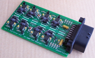
I have finally finished the assembly of the V2.1 box and made and verified the templates for the heatsink and case. I will make a web page soon but here a few preview pictures. Just as a reminder, this box contains 8 peak&hold drivers for low-Z injectors (could be assembled with fewer if wanted because they're all independent) and the drivers just require the standard injector grounding signal to control the drivers. So any standard MS ECU can be connected to this box without any modification as long as the injector output is specified as a high-Z output (no PWM). It will also work with the upcoming sequential board which does not have the PWM capability. It might also work with other ECUs.

Partially assembled board:
Image
Image

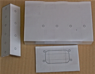
The case, heatsink, and endplate with the templates tapes to them before drilling. By the way, this is the first version of the endplate which is now changed because the board is in a lower slot to ease final assembly. The heatsink is a 4" long piece of aluminum 1/8" thick L-shaped 1"x1".
Image

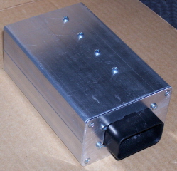
This is the completely assembled box.
Image

This is what the inside of the box looks like.
Image

And this is how the box compares, in size, to the MS case and the v2.0 box (4-driver box). The MS is about 6"x4"x 1.6", the V2.1 box is about 5"x3.2"x1.9", and the v2.0 box is about 4.7"x2.2"x.9". The V2.1 case is the same as the relay board case (EAS-200, with both halves).
Image

The BOM for the V2.1 can be found here. The connector is a bit expensive so if someone prefers a solution similar to the V2.0 could be used with wires soldered to the board and external connectors using rubber grommets to get the wires through the case endplate.

I have a few boards available and the cost will be $30 for the bare board plus shipping ($3 for US and Canada, $5 elsewhere, using regular mail in a padded envelop). If there is enough demand, I might consider doing partial or complete kits or maybe even assemble a few boxes but that won't be for right now.

EDIT: The board is no longer available.

Jean
Last edited by racingmini_mtl on Mon Sep 08, 2008 8:47 pm, edited 2 times in total.
jbperf.com Main site . . . . . . . . . . . . . . . . . . . . . . jbperf.com Forum
Image
RacerStev
MS/Extra Newbie
Posts: 23
Joined: Fri Jun 22, 2007 5:42 am

Re: Peak and hold injector driver board

Post by RacerStev »

I found a strange problem with my board today, seems when I add a pullup resister to either
input from the MS board my drivers seem to funtion normaly.

The problem I have been having is, no simutanius operation, only alternating. No injector output
past 50% duty cycle. With a 1K pullup off a 5 volt source all the problems seem to disapper. Any idea's?

Thanks Steve
racingmini_mtl
Super MS/Extra'er
Posts: 9127
Joined: Sun May 02, 2004 6:51 am
Location: Quebec, Canada
Contact:

Re: Peak and hold injector driver board

Post by racingmini_mtl »

First, which MS board do you have: v.2. or v3.0? Second, which FET driver do you have: IXDI404, MC34151, something else? Also, when you say you added a pull up, where did you add it? And how did you connect the board to your MS board and what did remove from the MS injector driver circuit?

It sounds like you may not have put the 5V supply to the FET driver when you removed the components from its 12V supply.

Jean
jbperf.com Main site . . . . . . . . . . . . . . . . . . . . . . jbperf.com Forum
Image
RacerStev
MS/Extra Newbie
Posts: 23
Joined: Fri Jun 22, 2007 5:42 am

Re: Peak and hold injector driver board

Post by RacerStev »

I have a v3.0 built by RS, I have the IXDI404. The pull up right now is off the 5 volt output of the stim to a 1K
resister, then it runs to one of the outputs from the MS board.

I can't say how it was connected or what was removed, RS did the mods for me. This is one of 2 boards they did
both have the same problem.

""""It sounds like you may not have put the 5V supply to the FET driver when you removed the components from its 12V supply.""""

I will look into this as best I can, kinda a noob with electronics.

Thanks Jean!
racingmini_mtl
Super MS/Extra'er
Posts: 9127
Joined: Sun May 02, 2004 6:51 am
Location: Quebec, Canada
Contact:

Re: Peak and hold injector driver board

Post by racingmini_mtl »

Check the voltage at pin 6 of U4 (IXDI404). This should be 5V.

If you want to know which components should not be there, you can have a look at this: http://jbperf.com/p&h_board/v30connect.JPG. The components that must not be present are: D3, D21, C13, C14, D17, D18, R15, R20. There are more details here: http://jbperf.com/p&h_board/index.html.

I'm a bit surprised that there are problems with RS built boards. I know they have done a few builds with my board. You should contact them to see what they have to say because you shouldn't have to be troubleshooting a custom built board.

Jean
jbperf.com Main site . . . . . . . . . . . . . . . . . . . . . . jbperf.com Forum
Image
RacerStev
MS/Extra Newbie
Posts: 23
Joined: Fri Jun 22, 2007 5:42 am

Re: Peak and hold injector driver board

Post by RacerStev »

I found it, there was no jumper running to pin 6. Ran 5 volts from the proto area and it fixed things
right up. I'll do some on the car testing later today, I'm optimistic we fixed it.

Sure will be nice to see the other 50% of my power range! LOL

And yes, I'll drop a line to RS and tell them what I found.

One more time, THANK YOU! You've been a life saver!

Steve
Post Reply