Here is an update:
I have completed the assembly of a 4 driver box except for the external connector but that will come soon. I will also do an 8 driver box as soon as I order the parts for it.
I have done the templates needed to correctly solder the transistors to the board and to drill the associated holes in the case. I have also done the templates for the needed heatsinks for the 2 board box. I have made 2 sets: one in imperial units and one in metric. The imperial are 1 3/4" long by 3/4" wide and can be either 1/16" or 1/8" thick. The metric are 47mm long by 20mm wide and can be either 2mm or 3mm thick. All holes are 1/8" (which is about 3.2mm). You need 2 pieces per board (so 4 for 2 boards). The templates are available as PDF files and need to be printed in 100% size. I have used the templates for my assembly. They are available here:
http://jbperf.com/p&h_board/v2_0/Inject ... _board.pdf for the board template for the transistor assembly and
http://jbperf.com/p&h_board/v2_0/Inject ... atsink.pdf for the drilling and heatsink templates.
I have a couple of pictures. This is how the board template is used for the transistor assembly (click for a larger picture):
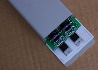
The endplates are used under the transistors because they are the same thickness as the case bottom and you can also see that I have put the mica insulators for proper positioning. In the single board box, there is no need for additional heatsinks, the board is in the second slot, and the transistor leads are inserted in the board from the bottom. I have cut the end of the printed template to solder the transistor in the correct position.
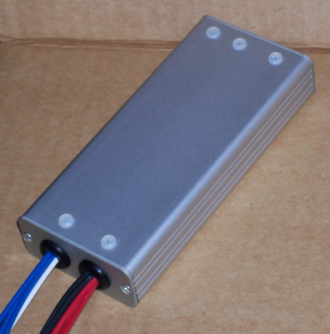
This is the assembled and closed box:

I have used nylon screws to attach the transistors to the case because that's what I had at hand but I recommend using metal hardware (which is what is in the BOM). You can also see that I have use 2 holes and grommets for the wires. On the left are the 4 injector control wires that go to the ECU (blue wires) with the 12V (white) and low current ground (black not visible in the picture). On the right are the 4 injector wires (red) and the 4 high current wires (black). The grommets are 1/4" rubber grommets which require 3/8" holes in the endplate. The wires are all 18 gauge TXL wires and the 6-wire bunch is just a tiny bit loose and the 8-wire bunch is a nice tight fit. All these wires will be connected to a single connector. And ideally I'd have different colors for each injector but that's what I have for now.
Jean