Knock Detection with variable sensitivity over RPM
Moderators: jsmcortina, muythaibxr
Re: Knock Detection with variable sensitivity over RPM
Multi-processor technology awesome.
One of those CPUs is the master. Or you using spi . I would have thought that with all those CPUs multitasking
speed would be your last area of concern. CPU for calculations,CPU for I/O . Great idea
One of those CPUs is the master. Or you using spi . I would have thought that with all those CPUs multitasking
speed would be your last area of concern. CPU for calculations,CPU for I/O . Great idea
Last edited by HOODEY on Sun Nov 13, 2011 8:57 am, edited 1 time in total.
Re: Knock Detection with variable sensitivity over RPM
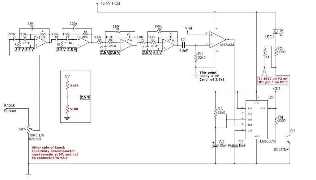
RPM and knock sensor KHz, the opamp converts the signal into a workable signal for the 16f PIC.HOODEY wrote:When you say count frequency are you refering to measuring rpm? Are you using DSp to process the knock signal. FFT etc?
I know that you read/write values from the tpic using a computer(?), but why not let the PIC do it all?
All my resistors and capacitors are surface mount.Curious about how you connect 4n25s to cam sensors. Do you a resistor?
Keep us updated and don’t be afraid to put your pictures back up, your posts look blank without them. It will inspire others to make something like it. (Like me)I have used a recording with knock to verify. I am Still testing like you as well.
Thanks. I am, I have so many of them. The 18f is twice as fast as the 16f series; I may go this route as well. I have several 18fs lying around along with several dspics, but i don't need the speed. (still looking into the dspic)Good work guy seems like you are well versed with PICs
-Rafiel
Re: Knock Detection with variable sensitivity over RPM
Having difficult reading TDC and POSTION signalS. If I read TDC signal as soon as I hook up the POSITION signal
engine starts to idle poorly. Any idea how to read the signal without affecting the ECU?
Re: Knock Detection with variable sensitivity over RPM
The PICs input pin should be high impedance; I’ve measured low, sensitive voltages with no problem many times. I used the 4n25(s) just to be on the safe side of things. (I know my cam sensor outputs like 20-60mv)
-Rafiel
Re: Knock Detection with variable sensitivity over RPM
Solved the problem by using a resitor to feedthe pin.
I was datalogging to flash memory but realised it can be very slow to write 8bytes of flash. So I write the data to the ram and then copy it to the flash memory.
The flash is full in about a second.
I think I wille be upgrading one more time to the pic18f2452 which has a faster ADC. Time is precious escpecially when a cylinder is firing every 120degress.
Re: Knock Detection with variable sensitivity over RPM
420aRaf can you show us what is displayed on your LCD.
I guess you are using the op amp connected to the pic as an integrator to integrate the knock signal.
Send me some 18f4520 man!!!!
Currently determing the time of various calcualtion subroutines. I have 990us to play with before the next cylinder fires(wrose case scenario).
I guess you are using the op amp connected to the pic as an integrator to integrate the knock signal.
Send me some 18f4520 man!!!!
Currently determing the time of various calcualtion subroutines. I have 990us to play with before the next cylinder fires(wrose case scenario).
Re: Knock Detection with variable sensitivity over RPM
Thanks hardware multiplier.
Just shaved 100us off the time.Major calculations are now down to 225us
Re: Knock Detection with variable sensitivity over RPM
Here are my old pictures I have from my first box, I don’t have any recent pictures of my 2nd box but it was a similar approach.HOODEY wrote:420aRaf can you show us what is displayed on your LCD.
KHZ = Frequency in KHz from knock sensor
LKCK = Last knock percentage tied in which uses an algorithm for ADC and KHZ multi oversampled in TDC; was just based on ADC.
WDO = Current rpm window, I also had a last knocking window
LCAM = Last cam experience knock – getting rid of this approach
Problem with this is that you would need a datalogg to find useful patterns, but other than that it worked well.
When all conditions are true:
If I tell you too much your project will be looking like mine. I have made progress myself between working on other projects. My current one focuses on knock counts and differences between samples. I now am using only one chip dedicated to processing and one for LCD. I could squeeze it all on one chip (18f2455) but I’m just too lazy. You may be able to process calculations fast but when working on one chip the major thing that eats up time is the live serial communication after every TDC samples. But I managed to do everything on the 16f887 so I’m going to move everything to the 18f. I am also going smaller with an 8x2 LCD. Keeping it as portable and simple as possible, so in other words I’m getting rid of the bling and displaying only numbers. Yeah, stuff gets tight at high rpm where I have to complete everything under 2 milliseconds. At the end of the day it comes down to how well it works on your engine not how fast you can process data although it's a small feat.
I don’t want this thread to be a HOODEY, 420aRaf knock detection thread. I just wanted to share what I made because of it.
EDIT: Nvm, if using hardware serial Uart it wont eat up time, and multiplying is indeed awesome!
-Rafiel
Re: Knock Detection with variable sensitivity over RPM
Cool. Completely different approach to me. I am about the bling and generic application factor.
Some of the terms used are bit confusing though. Why not use the term Cylinder? Also THD?
Wondering how you measure knock frequency as the signal from the knock sensor is packed with multiple frequencies.
Looking good though.
Some of the terms used are bit confusing though. Why not use the term Cylinder? Also THD?
Wondering how you measure knock frequency as the signal from the knock sensor is packed with multiple frequencies.
Looking good though.
Re: Knock Detection with variable sensitivity over RPM
Estimating Knock frequency based on cylinder bore diameter..
http://bajanchameleon.com/knockfreq.wmv
Re: Knock Detection with variable sensitivity over RPM
Trying to inpsire...
Last edited by HOODEY on Sun Nov 13, 2011 8:58 am, edited 1 time in total.
Re: Knock Detection with variable sensitivity over RPM
This goes back a little bit. How come the output of the 555 timer circuit is set for 0.4 of a second (1.1 * 39,000 * 0.000010)? There could be up to a hundred ignition events in that time frame.
MSII v3.0, Extra 3.0.3s
Re: Knock Detection with variable sensitivity over RPM
This products would be intended to use in a stand alone configuration, or maybe only work with the megasquirt?
In those mcu applications with external dsp's, are all decoding directly the trigger wheels?
This can be a quite difficult task, especially taking in account the there are a lot of trigger wheels around...
And add something to talk with megasquirt? Maybe using the tach output for AT LEAST the TDC and REV signal?
The tach output is fired at a fixed angle vs the TDC?
Reamain to decode the cam signal, for know what cylinder had det. Maybe this can be done directly in the ms3 firmware?
Enrico
Opel/Vauxhall Corsa GSi MS2
Subaru v4 EJ20 MS3
Opel/Vauxhall Corsa GSi MS2
Subaru v4 EJ20 MS3
Re: Knock Detection with variable sensitivity over RPM
In those mcu applications with external dsp's, are all decoding directly the trigger wheels?
This can be a quite difficult task, especially taking in account the there are a lot of trigger wheels around...
Correct..The sensible thing to do is to focus on the known well establisehd high performance vehicles.
-
- Helpful MS/Extra'er
- Posts: 50
- Joined: Thu Mar 12, 2009 11:01 am
- Location: Berkshire UK
Re: Knock Detection with variable sensitivity over RPM
well while you guys develop your own solutions i think it is only fair to test the already available and developed knocksense units that can be bought at a reasonable price.
I simply gave it power and connected it to my knock sensor.While revving my engine it indicated no knock events which I was happy with,but with the engine running if I hit the side of the engine block with a hammer it did indeed register this as knock,so it has passed this somewhat crude first test.
More testing to be done shortly.
Re: Knock Detection with variable sensitivity over RPM
Hi ,
where can the relatively cheap completed knock systems be purchased ,i have been trying to follow these post ,but is not able to get any information about any of these units.
Paul
where can the relatively cheap completed knock systems be purchased ,i have been trying to follow these post ,but is not able to get any information about any of these units.
Paul
-
- Site Admin
- Posts: 39619
- Joined: Mon May 03, 2004 1:34 am
- Location: Birmingham, UK
- Contact:
Re: Knock Detection with variable sensitivity over RPM
I can repair or upgrade Megasquirts in UK. http://www.jamesmurrayengineering.co.uk
My Success story: http://www.msextra.com/forums/viewtopic ... 04&t=34277
MSEXTRA documentation at: http://www.msextra.com/doc/index.html
New users, please read the "Forum Help Page".
My Success story: http://www.msextra.com/forums/viewtopic ... 04&t=34277
MSEXTRA documentation at: http://www.msextra.com/doc/index.html
New users, please read the "Forum Help Page".
Re: Knock Detection with variable sensitivity over RPM
Be pateint testing takes a lot of time.Especially in an automitive environment.
Last edited by HOODEY on Sun Nov 13, 2011 8:58 am, edited 2 times in total.
-
- Helpful MS/Extra'er
- Posts: 50
- Joined: Thu Mar 12, 2009 11:01 am
- Location: Berkshire UK
Re: Knock Detection with variable sensitivity over RPM
So ...the red line is the amount of spark retard at a given moment in time.
For every knock event the system is set to retard the timing by 3 degrees so at the point where i have the log set you can see i hit the engine three times in short sucession as the amount of overall ignition retard is nine degrees.You can see the rpm dropped slightly when the igniton timing was pulled along with the engine pulling slightly less vacuum(The blue line).As you can see the green line represents the actual amount of ignition timing seen at the flywheel.I want to just use the logging facilities already built into MS to analyse the data.
I am interested to see if there is a correlation between EGT's and det when i do some real driving testing once I get the car taxed this week.