Current ramp controller for Bosch 2-wire ISVs

A forum for discussing the MegaSquirt related (but non-B&G) board development, assembly, installation, and testing.

Moderators: jsmcortina, muythaibxr

Post Reply
Trev16v
Master MS/Extra'er
Posts: 420
Joined: Tue Apr 08, 2008 1:30 pm
Location: Oxfordshire, UK

Current ramp controller for Bosch 2-wire ISVs

Post by Trev16v »

Hi all,

I hope this is the most appropriate section to place this. I also want to say straight away that I may be changing where I host all my images and files shortly and so if any images or files are missing, please send me a PM.

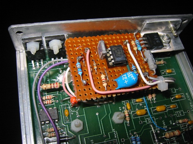
First of all here's an image of what I have produced, and an explanation shall follow.

Image

Background

My project is a 16V G60 engine which is currently in a Golf MK2, and will eventually be installed into my Golf G60 Syncro. I am running MS1 with MSNS-E 029v.

The standard VW 8V G60 engine runs a Bosch two-wire ISV, and I really wanted to be able to continue using such an ISV on my 16V G60. The Bosch ISV that I am using is the type that is supposed to be slightly open at 0% (to enable 'limp home' mode, I suspect); and closed at 25%. I can look up its part number if anyone requires it.

I initially had the ISV being controlled directly by the voltage PWM from the MS1 using a suitable power FET. Now I found that to have reasonably good resolution (steps) of duty cycle to the ISV, I had to drive the ISV at a frequency below 100Hz. To get usable resolution from the ISV I had to use a duty cycle of somewhere between 50 and 70Hz (I can't quite remember which). Although this did kind of work and did allow reasonable idle control, running at such a low frequency isn't the correct mode of operation for these ISVs. At this low frequency the piston in the ISV is just banging back and forth. I wouldn't have cared so long as it worked, but the ISV made an awfully loud noise that I couldn't stand.

The ISV should actually be operating at around 150Hz (the Digifant ECUs operate it at 147Hz). Because of the higher frequency, the piston isn't banging back and forth anymore. Instead it is 'suspended' at a point which obviously depends on duty cycle, and the ISV just makes a quiet buzzing noise - much more pleasant! The problem now though is that at this frequency, slight increases in DC appeared to open the valve up far too much, far too quickly. It was like this: At, for example, a DC of 20, the ISV might have given me 1000rpm. At 21, it might have been 1300rpm. You get the picture.

I made some measurements on a G60 that was running the standard Digifant ECU. I found that at idle, the ISV was getting what looked like 40% duty cycle (and when the engine was revved, the DC went down to 28% to close the valve and prevent boost going backwards through it). But if I attempted to give the ISV anything near this amount of duty on my engine, I'd totally rev the nuts off my engine. So this question was bugging the hell out of me: Why is it that the Digifant I controller can operate the ISV at around 40% duty at idle, and yet if I apply anything near that duty from the MegaSquirt controller, the engine revs far too highly?

So what I decided to do was reverse engineer the ISV control circuitry in both the Digifant II (8V GTI MK2) and Digifant I (G60) controllers. And I found the answer. The Digifant controller is not simply PWMing the ISV solenoid coil fully on and fully of. In actual fact, the controller is providing a controlled current ramp to the ISV.

When you scope the voltage across the ISV, you have a reasonably square waveform that looks like the ISV is just being switched on and off (G60 ECU PWM rate is 147Hz). But it isn't. For each PWM cycle during the 'on' period, the current in the ISV starts at some low value, and linearly ramps up. Then obviously during the dead time the current snaps to zero.

Why have Bosch controlled the ISV like this? Well, I have built a copy of the Bosch G60 ECU ISV circuit to fit into my MegaSquirt. When testing it on the bench, I've realised the following things:

1. The method of controlling the current through the ISV means that the ISV opening amount won't be affected by fluctuating battery voltage. Now initially I thought this wouldn't be important because surely the ISV closed loop control is going to compensate for supply voltage changes. But the problem comes when you apply throttle, which is the time when you want the ISV to be fully closed. At this time the ISV is no longer being closed-loop controlled; it has a fixed duty cycle applied (28%) in order to fully close it. If changing battery voltage (i.e. increased voltage from the alternator when you floor it) is able to affect the ISV opening then I suppose you could start losing boost through the ISV.

2. I've built an ISV tester board that allows me to vary the PWM to the ISV using up / down buttons. Now when I originally used this board to control the ISV by simply using on / off action using nothing more than a MOSFET, the ISV opening amount varied linearly with PWM duty. But, using the Bosch circuit, it's now more logarithmic. What I am finding is that the ISV is quite slow to open for up to 50 or 60% duty, but above that, it starts to open more and more. So why is this good? Well, I think that it means that for most of the duty cycle range, a wide duty range gives only a small ISV opening, with finer steps. This gives more precise ISV control and will give the MegaSquirt greater resolution to play with. But why is this better than simply shoving a resistor in series with the ISV? Well, the ISV is able to start opening by larger amounts if you swing the duty up to 80%. A large ISV opening is required during cranking. So: the ISV can be opened wide for cranking, but at the same time we have a great resolution of control around the point where the ISV just starts to open, allowing higher resolution of idle control. This is important on the MegaSquirt where the PWM resolution starts to become pretty poor when you start using frequencies like 150Hz.

Circuit Description

The circuit is simple to build. It consists of a MOSFET or NPN transistor that you'd typically chuck into the MegaSquirt in order to have ISV control. But we're no longer simply banging the device on and off. What the circuit introduces is a small value wirewound resistor in series with the transistor. This small value resistor (less than an ohm) and the FET/transistor now sit within the feedback loop of an operational amplifier. This means that whatever voltage is input into this op-amp determines the current flow through the ISV. The second bit is an op-amp integrator. This integrator provides a voltage ramp which controlled by the digital on/off PWM from the CPU.

So the circuit is quite simply a dual op-amp, a couple of capacitors, a few resistors, a little wirewound resistor that I stole from a scrap Digifant II ECU, and whatever MOSFET I could find amongst all my crap. The circuit fits onto a little 1.5" square bit of Veroboard.

PDF Schematic

http://www.introspectiv.eclipse.co.uk/1 ... V_r0_1.pdf

Conclusion

I know that many people have had success of driving a Bosch two-wire ISV straight from MS. I can only assume it's because those people are using MS2, which presumably offers much higher level of resolution and thus can voltage-PWM the ISV directly at 150Hz and still give small enough DC steps.

I am now getting good results from my ISV, although I still need to investigate a way of preventing the engine near-stalling when I operate the powered steering while the car is static.

I'll come back and edit this post shortly to refine it a little more. I'm quite tired now, so apologies if any of it doesn't make sense!

Cheers,

Trev
Golf MK2 G60 Syncro with 16VG60 on MSNS-E

MSDroid :: MegaSquirt tuning on Android

Image
matt_fulghum
Experienced MS/Extra'er
Posts: 167
Joined: Mon Sep 19, 2005 3:39 pm
Contact:

Re: Current ramp controller for Bosch 2-wire ISVs

Post by matt_fulghum »

d***, I just realized that I posted a very similar circuit to yours that I built for my own PWM valve, because of similar problems.

For a constant current source, I don't think you should use a MOSFET, because MOSFETs are meant for switching rather than for constant currents. I used a common TIP120 and it worked wonders... much more linear response than the MOSFET I initially tried. Also, you may want to make your first op-amp stage a very low frequency cutoff low-pass filter. This will get rid of any ripple from the PWM output of the MS.

I'm currently running 60 Hz PWM on my MS, with 0.4% step resolution as I recall, and it works great.

My circuit's at http://www.msextra.com/viewtopic.php?f=67&t=28953 if you're interested in how I built mine.

Good luck with the PWM idle valves... they can be tricky.

edit: another thing that you might be having trouble with is the fact that you can't reach 0V or 5V with your op-amps, because of the diode drops inside them. You may have more linear response if you use 12V to power the op-amps, which you may do however I can't tell from the schematic
Trev16v
Master MS/Extra'er
Posts: 420
Joined: Tue Apr 08, 2008 1:30 pm
Location: Oxfordshire, UK

Re: Current ramp controller for Bosch 2-wire ISVs

Post by Trev16v »

Hi Matt,

Thanks for the reply and your comments, and it's most interesting to know that you've worked on something similar.

The operational ampifier I have used is perfectly fine. If you look at the datasheet for the MCP6022, you'll see that it's a rail-to-rail type operational amplifier (MCP6022) which allows common mode inputs to be taken to virtually V- or V+ (0 to 5V), so input diode drops aren't an issue.

The current ramp is nice and linear. It's quite common for a FET to be used for a constant-current source. The transistor can be used as you suggested, but the FET is fine.

With regards to implementing an LPF, there is some hysteresis in my first stage so I don't think any ripple will make its way through. Our circuits are actually working in rather different modes. Your circuit converts the PWM into a stable DC voltage level (LPF), and converts that to a stable current. My circuit is different: it uses an integrator which produces a current that ramps up from 0 in a linear fashion for each period of the PWM. In other words, a sawtooth wave. The sawtooth is nice and linear without any curving or clipping. But the values must be matched to the frequency (about 150Hz in my case).

I *think* that an advantage of my solution *may* be that my ISV can respond to changing PWM faster. In real-world terms I don't think it will make any difference though. The main thing about the current-ramp approach though is that the amount of energy put into the ISV is logarithmic. You initially have very small opening changes for variations in PWM, but as the duty increases, the valve opens more and more. So even if you have pretty poor resolution (which you certainly do at 150Hz) you can have fine ISV control, yet still achieve ISV 'flare' during cranking (that's what the 'flare' means, right? I just want to check that).

Now that I am happy with the hardware aspects of driving the ISV, I think I want to re-write the idle PWM code part of the MS1 MSNS-E firmware. My engine idles reasonably well as it is without any help and so all I really need is open-loop warmup idle. But the problem I have is that operating the power steering when the car is stationary just pulls the revs right down and the engine nearly stalls. I don't know why other people don't have such a problem with power steering, but I am assuming it's because I have a lightened flywheel and so on (less inertia in the engine?). So I want to have closed loop ISV code that corrects this. I've struggled, without success, to get the standard closed-loop code to correct it.

Regards

Trev


Edit: Many multiple edits, sorry!
Last edited by Trev16v on Mon Nov 03, 2008 1:47 am, edited 1 time in total.
Golf MK2 G60 Syncro with 16VG60 on MSNS-E

MSDroid :: MegaSquirt tuning on Android

Image
matt_fulghum
Experienced MS/Extra'er
Posts: 167
Joined: Mon Sep 19, 2005 3:39 pm
Contact:

Re: Current ramp controller for Bosch 2-wire ISVs

Post by matt_fulghum »

Very clever with the rail-to-rail! I wish I had thought of that. Oh well, the parts I used on my board are conveniently common, which has made it handy for producing a bunch of them. Next time I design one I'll have to look into one of those. :)

I also have a lightweight flywheel and power steering that makes the engine lug a bit, but I'm running MS2/Extra which has really really nice closed loop idle code. Ever thing of swapping up?

And yeah, the flare effect is rather a rather convenient way to twist the non-linearity of the op amps I'm using. From 27% to 40% duty cycle, the voltage swings from about 3.00V (which is just before the valve starts to open for me) to 4.41V. This is pretty much the optimal operating range for the valve when the engine's running, and I get about 0.4% step resolution because of the low frequency output. Beyond that, 40% to 70% (where I crank at) goes from 4.41V to 8.06V, which is the flaring effect that you mentioned. All of this is at a constant 12.5V though.

When cranking, I assumed voltages would drop to about 10V, which on the bench shows around 6 volts to the valve at 70% duty cycle. This starts the car up very reliably, and then the closed loop idle kicks in and brings it back to a reasonable rpm. :)
Trev16v
Master MS/Extra'er
Posts: 420
Joined: Tue Apr 08, 2008 1:30 pm
Location: Oxfordshire, UK

Re: Current ramp controller for Bosch 2-wire ISVs

Post by Trev16v »

That's one advantage of having a constant current circuit - it becomes less dependent on battery voltage. Seemed to be when I tried the test circuit on the bench anyhow. I think that this *may* be more important for my application with the Bosch ISV, because the Bosch ISV is fully closed at something like 25%. So, I need to be able to say that when I apply 25% duty (or whatever it actually comes to in the real world), that the valve will always be properly closed at that duty, without the battery level messing things up. Otherwise I guess you'll have boost being lost through the ISV when you're on throttle. The fact that the op-amps are hanging off the logic rail means that battery voltage isn't going to muck up how they behave.

I didn't realise that the MS2-extra firmware has better closed-loop idle code. Now that you have said that, I think I'm going to order an MS2 kit!

Good to meet you by the way Matt - whereabouts are you in the world?

Cheers,

Trev
Golf MK2 G60 Syncro with 16VG60 on MSNS-E

MSDroid :: MegaSquirt tuning on Android

Image
matt_fulghum
Experienced MS/Extra'er
Posts: 167
Joined: Mon Sep 19, 2005 3:39 pm
Contact:

Re: Current ramp controller for Bosch 2-wire ISVs

Post by matt_fulghum »

better closed loop idle code AND it's under continuous development :)

I'm in the Boston, Massachusetts area. A little bit of a hop over the pond from you :P
Dennis930
Experienced MS/Extra'er
Posts: 187
Joined: Sun Feb 12, 2006 6:26 pm
Location: Va. Beach, VA

Re: Current ramp controller for Bosch 2-wire ISVs

Post by Dennis930 »

Trev,

Will this circuit work for a Bosch 3 wire valve?

Dennis930
Porsche 930 3.0 Slantnose
MS3/MS3X Sequential Injection & Spark, MS Knock, Dual plug, LS2 coils, Siemens 55 lb/hr HiZ injectors, ALM-ADV Wide Band,
Carrera Intake, Extrude honed, Ford 70mm Throttlebody, GTX3071R Turbo
Trev16v
Master MS/Extra'er
Posts: 420
Joined: Tue Apr 08, 2008 1:30 pm
Location: Oxfordshire, UK

Re: Current ramp controller for Bosch 2-wire ISVs

Post by Trev16v »

Dennis,

I'm afraid I don't know anything about the operation of the three-wire ISVs, I'm sorry. I've never personally had one to play with.

Trev
Golf MK2 G60 Syncro with 16VG60 on MSNS-E

MSDroid :: MegaSquirt tuning on Android

Image
django
Helpful MS/Extra'er
Posts: 36
Joined: Wed Mar 25, 2015 9:23 am

Re: Current ramp controller for Bosch 2-wire ISVs

Post by django »

hey
in your drawing, the entrance [ MS ISVpwm IN ]
where do i need to connect to the ms 1 V3 board ??

on the left is the old pwn draing strikethrough
the signal to be pick up here at B,, the MS motherboard

that is the question whether it should,,,else


henk
Last edited by django on Fri Oct 09, 2015 3:18 am, edited 1 time in total.
django
Helpful MS/Extra'er
Posts: 36
Joined: Wed Mar 25, 2015 9:23 am

Re: Current ramp controller for Bosch 2-wire ISVs

Post by django »

test75.jpg
Last edited by django on Fri Oct 09, 2015 3:03 am, edited 4 times in total.
django
Helpful MS/Extra'er
Posts: 36
Joined: Wed Mar 25, 2015 9:23 am

Re: Current ramp controller for Bosch 2-wire ISVs

Post by django »

test70.jpg
django
Helpful MS/Extra'er
Posts: 36
Joined: Wed Mar 25, 2015 9:23 am

Re: Current ramp controller for Bosch 2-wire ISVs

Post by django »

hello
which pin to conect the [ isv pwm in]
C,B,E
django
Helpful MS/Extra'er
Posts: 36
Joined: Wed Mar 25, 2015 9:23 am

Re: Current ramp controller for Bosch 2-wire ISVs

Post by django »

hallo
unfortunately with the schedule of ,trev16v,
if they catch anything with it
it,s like flogging a dead horse :evil:
jsmcortina
Site Admin
Posts: 39619
Joined: Mon May 03, 2004 1:34 am
Location: Birmingham, UK
Contact:

Re: Current ramp controller for Bosch 2-wire ISVs

Post by jsmcortina »

99% of customers are ok controlling these idle valves with regular PWM as that board-mod photo illustrates.

James
I can repair or upgrade Megasquirts in UK. http://www.jamesmurrayengineering.co.uk

My Success story: http://www.msextra.com/forums/viewtopic ... 04&t=34277
MSEXTRA documentation at: http://www.msextra.com/doc/index.html
New users, please read the "Forum Help Page".
Paul_VR6
Super MS/Extra'er
Posts: 1978
Joined: Wed Apr 15, 2009 11:31 am
Location: Oxford, PA
Contact:

Re: Current ramp controller for Bosch 2-wire ISVs

Post by Paul_VR6 »

Agreed and part of that 99% on a lot of installs (50+)
-Paul
1992 Corrado SLC 3.6 VR6 11.38@120 - MS3 Pro Ultimate - Microsquirt I/O - Can EGT - Racepak IQ3s
kptuned.com - Megasquirting the World! Megasquirt Sales, Service, Tuning and More!
Image
dontz125
Super MS/Extra'er
Posts: 4228
Joined: Mon May 11, 2009 7:14 pm
Location: York, ON
Contact:

Re: Current ramp controller for Bosch 2-wire ISVs

Post by dontz125 »

Django - connect to the C pin, or the FIDLE pin on the DB37.

On the 99% - yeah, this is one of those accessories that you don't need, unless you actually need it. Some have reported that a hard-to-tune idle valve suddenly plays nice with the addition of this circuit, but a lot more people have no issues. It's one of those things that you add -after- you try several other (non-hardware) options.
Temporarily shut down - back soon!
QuadraMAP Sensor Module -- PWM-to-Stepper Controller -- Dual Coil Driver
Coming soon: OctoMAP Sensor Module
TTR Ignition Systems
albo.c
MS/Extra Newbie
Posts: 1
Joined: Wed Oct 12, 2022 8:40 am

Re: Current ramp controller for Bosch 2-wire ISVs

Post by albo.c »

Hi everybody!
I want to resume this post to add my contribution.

I have had problems getting a stable idle on my abf swapped mk2 golf, so I took the idea of a current ramp controller and tried to make it better in terms of adaptability to different input signals.

Here i attach the schematic and the waves of the pilot signal and the resulting current in the ISV over time.
You do not have the required permissions to view the files attached to this post.
Paul_VR6
Super MS/Extra'er
Posts: 1978
Joined: Wed Apr 15, 2009 11:31 am
Location: Oxford, PA
Contact:

Re: Current ramp controller for Bosch 2-wire ISVs

Post by Paul_VR6 »

I wonder if there are different versions of this "same" idle valve with different behavior. There isn't a single one I have worked on in north america that I couldn't get working well with the standard TIP circuit and 1N4001 flyback or Micro with flyback or MS3 Pro PWM1
-Paul
1992 Corrado SLC 3.6 VR6 11.38@120 - MS3 Pro Ultimate - Microsquirt I/O - Can EGT - Racepak IQ3s
kptuned.com - Megasquirting the World! Megasquirt Sales, Service, Tuning and More!
Image
Post Reply