The CPU on the board will read the PWM from the MS2 output and keep the same duty cycle but multiply the frequency. I have tested it with the MS2/extra code from 11.1Hz to 78Hz with good results but it will work from about 8Hz to more than 300Hz. The output frequency can be chosen by setting jumpers and the resulting frequency multipliers can be 2, 4, 8, 16, 32, 64, 128, and 256. At an input frequency of 78Hz from the MS2 and a multiplier of 256, the PWM converter CPU will generate a 19968Hz PWM signal with a 0.25% resolution. So it's safe to say that any usable combination of input frequency and multiplier will not lose any precision. Also, the PWM duty cycle (and frequency) is updated for every cycle of the input signal so at 11.1Hz the output duty cycle is updated 11.1 times per second and at 78Hz the update is done 78 times a second. And the input is read with a 16-bit timer with 12 to 16 effective bits depending on the input frequency.
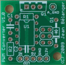
I have the boards in hand and components for a few kits. I have tested the code and the board and it looks like it's doing what it should be doing. The board looks like this:
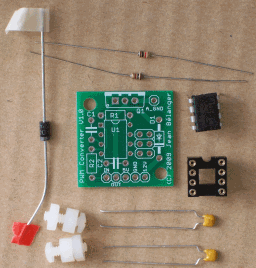
and the kit will include the following plus a TIP122 and mounting kit with insulator which is not in the picture:
I have tested the board on the FIDLE and JS11 outputs with the FIDLE signal and the boost control signal. The board needs a 5V signal and cannot take a 12V signal so if you're using one of the IAC outputs, you will need to do something about this. You could use a voltage divider (2 resistors) to reduce the voltage. One thing that I need to try is if the UDN2916 can be fed with 5V instead of 12V (on JS9) which would make this as easy way to have a 5V signal.
As mentioned in the other thread, the kit is $15 plus shipping and includes everything needed to make this work (except wires) and to mount it on the MS case. I will be making a web page on my site with all the details but don't hesitate to post any question.
Jean