The V2.1 board still has the same circuit as the V2.0 but has a new form factor. It is smaller and the pads are placed such that they fit a DIP8 pattern. So you can use a DIP8 socket or solder it directly to a proto area or a perforated board. It still has the two mounting holes so you can still solder wires directly to the board.
It also now comes in two versions: the internal and the external versions. The internal version is for those who want to use it in the ECU case and it doesn't have the on-board voltage regulator and needs to be powered by a 5V source. The external version has an on-board voltage regulator and can therefore be powered by a 12V source from the car. However you still need to put it in some sort of enclosure to protect it from the environment (as it was for the V2.0).
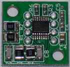
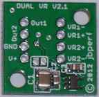
This is what the board looks like:
 .......
 .......
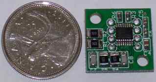
You can see the top of the board with the MAX9926 circuit and the current limiting resistors are now a bit bigger to withstand more voltage from the sensor (the ones on the V2.0 are sufficient in almost all cases but this is for more margin). The bottom has the optional voltage regulator and the labels indicate the pinout. The third picture shows the size relative to a Canadian quarter (same size as a US quarter).
The external version is the same price as the V2.0 ($45 plus shipping) but the new internal version is cheaper ($35 plus shipping).
For now you can contact me to buy them directly from me.
Jean