Arduino-based CANbus gauge

A forum for discussing the MegaSquirt related (but non-B&G) board development, assembly, installation, and testing.

Moderators: jsmcortina, muythaibxr

bittertech
MS/Extra Newbie
Posts: 19
Joined: Thu Jun 23, 2011 5:27 pm

Arduino-based CANbus gauge

Post by bittertech »

I've been working on this for the last couple of months, and it's nearly complete - thought it was time to finally unveil. I've made a lot of additional progress this winter break, but not quite enough to warrant a new video. Make sure you enable 1080p to see the detail on the youtube video. There isn't any noticeable flicker in the gauge (artifact from my camera) and the colors are hard to capture - I had to load up with a circular polarizing and UV filter to get this shot.

Image

http://www.youtube.com/watch?v=zidmpnja-kU

I'm using a Sparkfun CANBus shield to communicate to the MS. The gauge is a gutted ebay gauge, Adafruit Neopixel ring, Adafruit 1.3" OLED screen. I originally tried to use a cheaper arduino, but the OLED screen requires about 1.5k of ram and arduino's usually only have 2/2.5k. I'm currently working on getting my LC-1 to talk to it (I've got another benchtop setup talking to the LC-1, but I'm still looking at how to get the data into MS cleanly - is it best to have MS poll like whats done in the tinyiox board? Or can I do a msg_cmd and write directly to MS?)

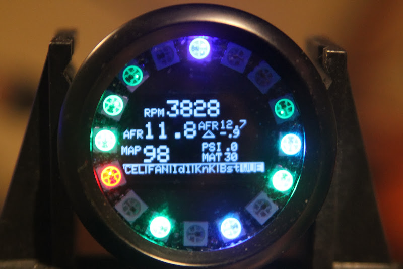
Each LED responds to a 1-1000 color gradient that I normalize to a variable. The 12 o'clock position is the delta between the AFR and AFR target - so that green is close, blue is rich, red is lean. 9-11:30 is RPM, 12:30-3 is AFR. 8:30 is TPS, 6:30 is CLT. At > 240f it begins to blink, at 260 the entire gauge turns red and the value is shown in the screen center. 5:30 is MAT, 3:30 is MAP. I've got 3 extra LED's that will be monitoring oil pressure, oil temperature, and EGT once I wire my PLX Gauges into the MS (since I've got a spare com port on the mega, I might try a crack at reading the PLX datastream and writing to MS - or I might just go with the generic 0-5v and save me some coding). This allows me quick "at a glance" to see if everything is running within bounds (I might change some of this logic once I get the gauge in the car so I'm not distracted by red lights - I'm waiting on some final harnesses so I can pop everything in and out cleanly).

I've made a few additional functions since I made this video - for instance, if RPM > 6800 and TPS > 90, the outer ring becomes a shift light for the last 800 RPM I have till I hit my rev limit.

Image

Menu's are controlled via a rotary encoder I've got bolted into my fuse box cover. Pushing down on it changes the menu or selects the item, while turning it flips through different values. There are 3 different menu's shown in the video. The histogram was added pretty much "because I could" - I've never found it useful with my PLX gauge. The dotted line in the middle represents 14.7 in AFR or Barometer in MAP. I've also included a high/low on the single item view for a couple of variables - the values expire after 30 seconds, though I might play with that value some.

I *think* I'm the first person to talk to megasquirt via the MCP2515 canbus transceiver, and I've tried to document the project and talking to arduino at kckr.net (forgive me, I'm still documenting and finishing up the gauge so it's still incomplete). I've published some example code for communicating with the MCP2515 at github, and once I get the featureset finished and clean up my awful terrible code I'll publish that as well.

Overall, I think I've got about $200 in parts for this gauge (the Canbus shield at $45 and the Mega at $56 being the largest two expenses). I've been thinking about possibly seeing if I could make this more affordable by going with an AT90CAN (at $14 to replace the mega and shield... yeah, economically way better). This has been my largest electronics project to date and it's been a lot of fun and frustration.

So - before I put a fork in this and call it done - any features y'all think would be cool to add?
knightrous
Experienced MS/Extra'er
Posts: 153
Joined: Tue Oct 06, 2009 4:58 pm
Location: NSW, Australia
Contact:

Re: Arduino-based CANbus gauge

Post by knightrous »

Have you considered looking at the Teensy 3.1 board as a replacement for the Arduino and shield?
The Teensy 3.1 has CANbus built in, has oodles of programming space (256K), plenty of grunt for a small board (72Mhz / 64K), very low cost (US$19.80) and can easily be programmed using the Arduino IDE.
'89 Toyota MR2 AW11 - 1MZFE 3L V6 - Need to finish car before ecu :(
'89 Toyota MR2 AW11 - 16V 4AGZE - DIYPNP 1.5v
'90 Toyota MR2 SW20 - 1MZFE 3L V6 - MS3X
bittertech
MS/Extra Newbie
Posts: 19
Joined: Thu Jun 23, 2011 5:27 pm

Re: Arduino-based CANbus gauge

Post by bittertech »

Awww man.. that MCU looks much nicer. All the gauge really needs output-wise is I2C for the gauge and a highspeed gpio for the neopixel, and some interrupts for the rotary encoder. Truth be told, I've had these parts sitting on my shelf since before ShadowDash came out.
racingmini_mtl
Super MS/Extra'er
Posts: 9130
Joined: Sun May 02, 2004 6:51 am
Location: Quebec, Canada
Contact:

Re: Arduino-based CANbus gauge

Post by racingmini_mtl »

I think the CAN bus on the Teensy is not yet supported by the Arduino IDE but it is planned. One problem is that it is a 3.3V board (with 5V tolerant inputs) so you have to use peripherals that can deal with it or use level shifters. But a 32-bit processor with 64K of RAM working at 72MHz is quite a beast compared to the garden variety Arduino.

Jean
jbperf.com Main site . . . . . . . . . . . . . . . . . . . . . . jbperf.com Forum
Image
Suprazz
Master MS/Extra'er
Posts: 500
Joined: Mon Jan 22, 2007 7:58 pm
Contact:

Re: Arduino-based CANbus gauge

Post by Suprazz »

Nice job! I was looking to implement something like this with a 1.5" oled color screen. But I dont plan to work on this in the next few months because I've to many projects going on.

To lower cost of the gauge Maybe you should try to build your own board when your prototype is ready instead of buying many electronic parts. Board design is not that hard and you can make pcb really cheap with seeedstudio. This way you will only have to buy electronics part that cost almost nothing and do the welding.

When you have one ready let me know It's a really interesting product and I would really like to try it!

Sam
Best looking and most advanced CAN-bus gauge
Toyota Supra 7MGE, 7M-GTE and 1JZ-GTE Plug and play ECUs: http://www.perfecttuning.net
Serial to Bluetooth or Serial to WiFi
DIYAutotune Canadian, EFI Source and ECUMaster reseller!
bittertech
MS/Extra Newbie
Posts: 19
Joined: Thu Jun 23, 2011 5:27 pm

Re: Arduino-based CANbus gauge

Post by bittertech »

Yeah - I started looking more into the teensy and it looks like there isn't a library for CAN.. yet. I saw estimates of getting it working sometime in March. If anything though I hope I've provided enough documentation at
http://kckr.net/interfacing-megasquirt-with-arduino/ to help someone get their request/response working without the numerous pitfalls I ran into (really need to get off my butt and finish everything). The code always seems to need a refactor though. But if you wanted to drive something like a character-based LCD this should work.

Though using that cortex with 64k of SRAM? You could drive a really nice full color screen with that.

And just in case I buried my question within the first post - is there an easier way to write AFR to megasquirt, or would it behoove me to set it up like a tinyiox?
racingmini_mtl
Super MS/Extra'er
Posts: 9130
Joined: Sun May 02, 2004 6:51 am
Location: Quebec, Canada
Contact:

Re: Arduino-based CANbus gauge

Post by racingmini_mtl »

bittertech wrote:And just in case I buried my question within the first post - is there an easier way to write AFR to megasquirt, or would it behoove me to set it up like a tinyiox?
The reason it's done the way it is in the TinyIOx is because the MS code expects it that way.

Jean
jbperf.com Main site . . . . . . . . . . . . . . . . . . . . . . jbperf.com Forum
Image
420aRaf
Helpful MS/Extra'er
Posts: 59
Joined: Thu Feb 19, 2009 4:33 pm
Location: Staunton, VA

Re: Arduino-based CANbus gauge

Post by 420aRaf »

bittertech, thanks for the documentation. Any idea on your typical update time in milliseconds it takes to complete a read/write canbus cycle? What’s the max read/write speed you would see from a MS2 or MS3? I would like to use the MCP2515 on my current LCD panel.

Maybe you could look into the AT32 cpu to drive everything, that should have plenty of speed and flash to look up ascii characters. You could store all of your ascii info and arrays for the oled/lcd in its 16-256k flash. The MCP2515 is rather cheap (under 2 bucks) considering everything it does. You could make your own boards including the o-led, cpu, leds and can bus module for under ~$50 in raw materials. I soldered the small oled ribbon on a board by hand with some flux and a pencil tip soldering iron. Cost per board was under $10 fully assembled in raw materials.

Edit: Updated chip...from atmega32 to AT32...quite a difference :mrgreen:
-Rafiel
bittertech
MS/Extra Newbie
Posts: 19
Joined: Thu Jun 23, 2011 5:27 pm

Re: Arduino-based CANbus gauge

Post by bittertech »

It's not the strings that drive memory consumption, most everything static is using progmem to keep consumption down. The OLED display is buffered on the arduino which eats up the 1.5k. I've used a couple of tricks like storing the raw data from the MS as chars or ints, converting them to strings, printing the string, then reusing the string for the next variable to keep the memory usage down - but it kept acting "weird" so decided it was worth my time (and sanity) to spend the extra $30 than chase my tail for another week.

I benchmarked my screen writes when I noticed a weirdness while making the historgram gauge - as the gauge was filling up, the screen updates were slowing down significantly. I ended up finding an alternative ssd1306 library that fixed a slow drawline routine, dropping screen refreshes from 200ms to 80ms (plus tx/rx's)

The MS documentation, iirc, says that about 600 canbus packets per second - so that's ~300 request/receives

Thanks Jean - I'm running into some problems now with the EGO-Can working - with MS requesting, it's absolutely spamming the bus with request packets (and breaking my code by throwing interrupts everywhere). I haven't quite figured out what the response packet should look like - so far I've got that it's requesting 8 bytes to block 7 offset 605. I've been tossing data at the MS but I haven't yet seemed to crack it - still looking through the source to understand datax1 construct.
bittertech
MS/Extra Newbie
Posts: 19
Joined: Thu Jun 23, 2011 5:27 pm

Re: Arduino-based CANbus gauge

Post by bittertech »

Okay, that was slightly annoying - but I finally cracked the LC-1 serial -> CAN. The MS is requesting block 7 offset 605 - but it appears as though you need to subtract 8 bytes and shove data back at offset 597 and after some mucking about, I think it's requesting the lambda data like the LC-1 stores. Looks like I can continue to write up a timing function to pull the uart every 82ms and push that data across the wire. Wewt.
racingmini_mtl
Super MS/Extra'er
Posts: 9130
Joined: Sun May 02, 2004 6:51 am
Location: Quebec, Canada
Contact:

Re: Arduino-based CANbus gauge

Post by racingmini_mtl »

You either have something not set correctly or you're not reading the request messages correctly or you're not creating the response messages correctly because you should use the requested offset in your response without having to add or subtract anything.

There's always the possibility that there is a bug in the MS firmware that hasn't been identified so you could try using an earlier version that has been tested. This is especially true if you're using an alpha or beta version.

Jean
jbperf.com Main site . . . . . . . . . . . . . . . . . . . . . . jbperf.com Forum
Image
bittertech
MS/Extra Newbie
Posts: 19
Joined: Thu Jun 23, 2011 5:27 pm

Re: Arduino-based CANbus gauge

Post by bittertech »

My MS3 is still using 1.2.3, so I don't think it lies there - but it does leave me scratching my head. I wrote a different program that I tossed on another arduino to decode packets / verify my information down the wire. For example -

Idle target - block 7, offset 380. I copy the offset/block to be my destination and get the return packet (arduino's can_id = 3)

Image

The top packet data buffer has the source/destination in it -

b00000111 = block 7
b00101111
b100
00010 = 2 bytes

b101111100 = 380 offset

response packet from MS mirrors that, so I think my decoder is proved.

Turning on "Fetch Innovate data via can" on canID 3, table 7, offset 80 -

Image

another thing that's odd - it's added 8 to the requesting offset (this is what initially tipped me to trying subtracting 8 on my response).
Second thing that's odd -

b00000111 = table 7
b01001011
b101
01000 = requesting 8 bytes

01001011101 = 605. Tossing data back there doesn't work - so what does work is 597.

Image

offset 597, block 7, 8 bytes. MS reads this as 13.00AFR in tunerstudio (384 lambda - which if 500 = 14.7, I think is mostly sane). So yeah - don't know why.

I did try playing around with non-EGO canadc earlier, and those seem to be okay (didn't spend long on them). request came from 512, i sent data at 512, tunerstudio gauge jumped around some. Really odd. *shrug*
bittertech
MS/Extra Newbie
Posts: 19
Joined: Thu Jun 23, 2011 5:27 pm

Re: Arduino-based CANbus gauge

Post by bittertech »

Code: Select all

       // Innovate EGO via CAN
        // currently only supported by Extender
        if (ram4.can_poll2 & 0x01) {
            for (ix = 0 ; ix < 2 ; ix++) {
	            can[1].cx_msg_type[can[1].cxno_in] = MSG_REQ; 
	            can[1].cx_dest[can[1].cxno_in] = ram4.can_ego_id;

	            can[1].cx_destvarblk[can[1].cxno_in] = ram4.can_ego_table;
	            // 1 input
	            can[1].cx_destvaroff[can[1].cxno_in] = ram4.can_ego_offset + (ix * 8);
	            can[1].cx_varbyt[can[1].cxno_in] = 8;

	            // where should the resulting data be stored
	            can[1].cx_myvarblk[can[1].cxno_in] = 7;  // store returned data in outpc (datax1)
	            can[1].cx_myvaroff[can[1].cxno_in] = 512 + (unsigned short)(&datax1.ego[ix*4]) - (unsigned short)(&datax1);

                can_inc_ring(1);
            }
        }
It almost looks like the +8 is intentional (assuming ix = 1) comparing to the other CAN ADC function in ms3_can.c - but I'm scratching my head as to why. I tried looking through the extenders code for some explanation, but it just left me more confused.
racingmini_mtl
Super MS/Extra'er
Posts: 9130
Joined: Sun May 02, 2004 6:51 am
Location: Quebec, Canada
Contact:

Re: Arduino-based CANbus gauge

Post by racingmini_mtl »

The +8 is for the second packet. For the first packet, ix = 0 so there is nothing added to the offset.

Jean
jbperf.com Main site . . . . . . . . . . . . . . . . . . . . . . jbperf.com Forum
Image
xrattiracer
Experienced MS/Extra'er
Posts: 301
Joined: Fri Aug 01, 2008 2:25 pm

Re: Arduino-based CANbus gauge

Post by xrattiracer »

bittertech, have you done any further work to this yet? I've also been looking around for your github and can't find it.
I have had a back burner project going that is similar, but using the Switec X27.168 steeper motors used to drive the needles in almost every oem dash cluster nowadays.
burdickjp
Helpful MS/Extra'er
Posts: 72
Joined: Thu May 24, 2012 4:19 am

Re: Arduino-based CANbus gauge

Post by burdickjp »

richyvrlimited
Master MS/Extra'er
Posts: 568
Joined: Mon Jun 26, 2006 1:03 pm
Location: Warrington, NorthWest England

Re: Arduino-based CANbus gauge

Post by richyvrlimited »

burdickjp wrote:I did something kinda like this.

http://grassrootsmotorsports.com/forum/ ... 878/page1/


Looks very very good.

Would you be willing to share your code? I'm just starting out on my own Arduino based gauge. I've no interest in copying your work FWIW, more reading your code to learn how I might achieve it myself.

Many thanks
2003 MX5. Coldside MP62
-
MS3, RTC, & Knock board, Release 1.2. LC-1 Wideband.
burdickjp
Helpful MS/Extra'er
Posts: 72
Joined: Thu May 24, 2012 4:19 am

Re: Arduino-based CANbus gauge

Post by burdickjp »

richyvrlimited wrote:
burdickjp wrote:I did something kinda like this.

http://grassrootsmotorsports.com/forum/ ... 878/page1/


Looks very very good.

Would you be willing to share your code? I'm just starting out on my own Arduino based gauge. I've no interest in copying your work FWIW, more reading your code to learn how I might achieve it myself.

Many thanks
It is linked in the last post of the thread: http://pastebin.com/nA34ZM3b

And please, if you find it useful, use it. I'm very much an open source advocate.
acab
Experienced MS/Extra'er
Posts: 243
Joined: Tue Aug 21, 2012 5:52 am

Re: Arduino-based CANbus gauge

Post by acab »

where i can get more info about project?
walterclark1
Experienced MS/Extra'er
Posts: 292
Joined: Tue Jan 01, 2013 3:37 pm
Location: Dover, MA., USA

Re: Arduino-based CANbus gauge

Post by walterclark1 »

xrattiracer wrote:bittertech, have you done any further work to this yet? I've also been looking around for your github and can't find it.
I have had a back burner project going that is similar, but using the Switec X27.168 steeper motors used to drive the needles in almost every oem dash cluster nowadays.
I made an X27 based speedometer with the Arduino but driven from a MS VSS output. Story is here: http://www.hillclimb.org/forum/viewtopi ... =16&t=1133
A2 VW GTI 9A - MS3/3X
Post Reply