I've been using a DIYPNP kit to run a 1988 Toyota 4AGE MR2 Lemons car with an IHI RHB5 home-made turbo setup, using low impedance 450cc injectors with resistors.
The DIYPNP kit uses a V2.2M Microsquirt card on a V1.5B circuit board:
https://www.diyautotune.com/diypnp/apps ... ge-mt.html
It looks like the peak & hold driver board may work with the ecu if I can manage to make the connections.
I plan to mount the p&h board and transistors to an aluminum plate that slides into the large DIYPNP case.
I am using the board assembly instructions here:
http://jbperf.com/p&h_board/index.html
For connections, JB has advised:
"... leave off 2 resistors from the board since there are some on the Microsquirt module; these are for drivers 1 and 2. Drivers 3 and 4 do need the resistors since the circuits on the module are not identical."
And:
"You will also need to connect the JP1 input pads on the p&h board to the J1 header on the Microsquirt module (there is most likely a place on the DIYAutotune board where this header is repeated; I think this is close to a proto area). ALT_INJ1, ALT_INJ2, PT6, PT7 connect to pads 1, 2, 3 and 4 on the p&h board. This assumes you will use sequential injection.
You will also need to connect the p&h board injector outputs to the injector outputs on the DIYAutotune board. I assume that these are the pads connected to the ECU connector so you will have to see which connector pin corresponds to which injector. The injector outputs on the p&h board are labeled INJ1, I2, INJ3, INJ4 and they correspond to the inputs 1 to 4 (note that the ECU fires the outputs in the order 1,2,3,4 so you need to connect the injector in the correct firing order). You also need to connect the injector grounds (IGND1 to 4) to a ground pin on the ECU connector."
JB mentioned sequential injection. I'm confused. Since the Microsquirt board only has two injector outputs, and I have four cylinders, doesn't that require some kind of batch firing?
I am about to go assemble the board, and hopefully find my connections.
P&H board for DIYPNP Microsquirt MR2
Moderators: jsmcortina, muythaibxr
P&H board for DIYPNP Microsquirt MR2
DIYPNP MS2 1989 MR2 turbo Lemons car, MS3 Pro 1971 Riviera turbo LQ4, MS2 1992 Humvee Chevy 350, MS3 Pro 98 F150 5.8 turbo
-
racingmini_mtl
- Super MS/Extra'er
- Posts: 9130
- Joined: Sun May 02, 2004 6:51 am
- Location: Quebec, Canada
- Contact:
Re: P&H board for DIYPNP Microsquirt MR2
You can have 4 injector outputs if you use the connections I mentioned and you configure the settings accordingly. However, you will need to have a cam speed tach input for that. If you only have a crank tach input, you're limited to batch or semi-sequential injection. In this case, you will need to connect 2 drivers to ALT_INJ1 and 2 drivers to ALT_INJ2 and leave PT6 and PT7 unconnected.
And don't solder any connection until you're certain you have what you need.
Jean
And don't solder any connection until you're certain you have what you need.
Jean
Re: P&H board for DIYPNP Microsquirt MR2
I have soldered the p&h board components with the board and transistors mounted to an aluminum heat sink, and it should be ready to go in the case.
I do not know where to look to find the injector 1 & 2 resistors or ALT_INJ1 or ALT_INJ2. I did manage to find PT6 and PT7 in two places on the board.
I am using a Toyota VAST distributor signal for Megasquirt ignition control. Will that work for sequential?
I do not know where to look to find the injector 1 & 2 resistors or ALT_INJ1 or ALT_INJ2. I did manage to find PT6 and PT7 in two places on the board.
I am using a Toyota VAST distributor signal for Megasquirt ignition control. Will that work for sequential?
DIYPNP MS2 1989 MR2 turbo Lemons car, MS3 Pro 1971 Riviera turbo LQ4, MS2 1992 Humvee Chevy 350, MS3 Pro 98 F150 5.8 turbo
-
racingmini_mtl
- Super MS/Extra'er
- Posts: 9130
- Joined: Sun May 02, 2004 6:51 am
- Location: Quebec, Canada
- Contact:
Re: P&H board for DIYPNP Microsquirt MR2
The resistors I was mentioning are R10 to R13 on the p&h board. This are not needed if you connect the board to ALT_INJ1 and ALT_INJ2. If you have already installed them, leave them there; they will not have an impact in this configuration.
The picture below gives you an idea of what I was saying about the connections to the board (ignore the schematic part which is from a different MS board from what you have). So you would connect ALT_INJ1 to the first 2 pads on the bottom and ALT_INJ2 on the next 2. Then you need to connect to a ground and 5V on your DIYPNP board to power the p&h board
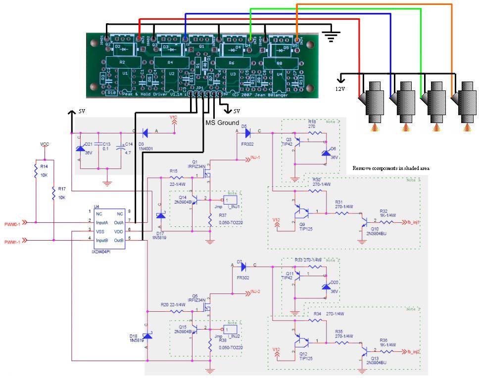
And you need to contact DIYAutotune (or they may answer here) to see if you can do sequential with your DIYPNP and where ALT_INJ1 and ALT_INJ2 are located on you board. I have no information on the DIYPNP other than generic high level information and there is no schematic publicly available that I'm aware of. And I have never had one in my hands or even seen one other than in pictures.
Jean
The picture below gives you an idea of what I was saying about the connections to the board (ignore the schematic part which is from a different MS board from what you have). So you would connect ALT_INJ1 to the first 2 pads on the bottom and ALT_INJ2 on the next 2. Then you need to connect to a ground and 5V on your DIYPNP board to power the p&h board
And you need to contact DIYAutotune (or they may answer here) to see if you can do sequential with your DIYPNP and where ALT_INJ1 and ALT_INJ2 are located on you board. I have no information on the DIYPNP other than generic high level information and there is no schematic publicly available that I'm aware of. And I have never had one in my hands or even seen one other than in pictures.
Jean
-
Matt Cramer
- Super MS/Extra'er
- Posts: 17507
- Joined: Thu Apr 16, 2009 8:08 pm
Re: P&H board for DIYPNP Microsquirt MR2
The alternate injector outputs are labeled "Logic Level Inj" 1 and 2 on the 18 pin header behind the DB9.
Matt Cramer -1966 Dodge Dart slant six running on MS3X
Re: P&H board for DIYPNP Microsquirt MR2
OK, I see the logic level inj 1 & 2 outputs. They show on the board photo above, middle right.
On the DIYPNP connector board, pins C1, C2, and C3 are not being used. Pin C4 and C9 are the injector outputs. C5, C10, and C7 go to the V1.5 board ground. I need to check the engine harness to see if they are the injector grounds. The 4AGE firing order is 1-3-4-2.
For sequential injection, I plan to:
1. Connect the V1.5 board outputs: Logic Level Inj1, Logic Level Inj2, PT6, and PT7 to the first 4 inputs on the bottom of the P&H board.
2. Connect the V1.5 ground to the next P&H input.
3. Connect the V1.5 +5V to the last P&H input.
4. Disconnect the V1.5 board Inj1 and Inj2 outputs from C9 and C4.
5. Run the P&H outputs to C1, C2, C3, and C4.
6. Re-do the engine harness so C1-4 go to injector 1-3-4-2.
7. Check the grounds.
If that's all it takes it seems simple now.
DIYPNP MS2 1989 MR2 turbo Lemons car, MS3 Pro 1971 Riviera turbo LQ4, MS2 1992 Humvee Chevy 350, MS3 Pro 98 F150 5.8 turbo
-
racingmini_mtl
- Super MS/Extra'er
- Posts: 9130
- Joined: Sun May 02, 2004 6:51 am
- Location: Quebec, Canada
- Contact:
Re: P&H board for DIYPNP Microsquirt MR2
That should be it for the hardware side. You will then need to make sure you enable the additional drivers in your settings in TunerStudio and enable sequential injection.
You can test your hardware connections using the test mode. Make sure each injector fires in the correct order.
Jean
You can test your hardware connections using the test mode. Make sure each injector fires in the correct order.
Jean
Re: P&H board for DIYPNP Microsquirt MR2
Here it is soldered together.
DIYPNP MS2 1989 MR2 turbo Lemons car, MS3 Pro 1971 Riviera turbo LQ4, MS2 1992 Humvee Chevy 350, MS3 Pro 98 F150 5.8 turbo
Re: P&H board for DIYPNP Microsquirt MR2
I'm having trouble with the Tuner Studio setup. The menus are slightly different that what is shown here:
http://www.jbperf.com/sequential/
The Sequential settings are in Basic/Load Settings. I "Enabled Additional Drivers" but the sequential settings are grayed out.
In "Boost/Advanced" "Programmable Outputs" there is an option to enable ports PT6-IAC1 and PT7-IAC2. Should I do that, and what are the port settings?
I have the ECU on the bench. Whenever I power it up the TPS indicator slowly moves up past 100%. I have about 15 seconds before it maxes out and keep going. I've been shutting it off when it gets up. Should I worry about this?
Do I need to do any physical modifications to the Microsquirt card?
DIYPNP MS2 1989 MR2 turbo Lemons car, MS3 Pro 1971 Riviera turbo LQ4, MS2 1992 Humvee Chevy 350, MS3 Pro 98 F150 5.8 turbo
-
racingmini_mtl
- Super MS/Extra'er
- Posts: 9130
- Joined: Sun May 02, 2004 6:51 am
- Location: Quebec, Canada
- Contact:
Re: P&H board for DIYPNP Microsquirt MR2
Look in the manual: http://www.msextra.com/doc/pdf/html/Meg ... .4-69.html
And you don't want to use PT6 and PT7 for another function so why would you enable them there? So don't do that.
And don't worry about the TPS; that's what happens if nothing is connected to its input. You can always just ground the input while it's on the bench.
And there is no need to modify anything on the Microsquirt module.
Jean
Re: P&H board for DIYPNP Microsquirt MR2
I am very grateful for the help. This is difficult for me. I read the linked pages, and some other entries on ignition settings:
http://www.megamanual.com/ms2/vast.htm
http://www.msextra.com/doc/pdf/html/Meg ... 4-101.html
I have been running the car with the ignition setting on basic trigger. That does not enable sequential injection. The distributor has a four tooth and a single tooth wheel. Do I set the ignition for dual wheel?
DIYPNP MS2 1989 MR2 turbo Lemons car, MS3 Pro 1971 Riviera turbo LQ4, MS2 1992 Humvee Chevy 350, MS3 Pro 98 F150 5.8 turbo
-
racingmini_mtl
- Super MS/Extra'er
- Posts: 9130
- Joined: Sun May 02, 2004 6:51 am
- Location: Quebec, Canada
- Contact:
Re: P&H board for DIYPNP Microsquirt MR2
If you want sequential injection, you need to set it as a dual wheel. One problem I'm worried about looking at the picture is that the single tooth seems to be aligned with one of the 4 teeth. As long as the single tooth is always before the same tooth, it's ok but if there is the slightest jitter either on the hardware or in the signal from the electronics or due to the code then it won't work.
I'm not familiar with this specific setup but there has to be others using this on the forum who are and could comment on it. DIYAutotune might also be able to confirm one way or the other.
Jean
I'm not familiar with this specific setup but there has to be others using this on the forum who are and could comment on it. DIYAutotune might also be able to confirm one way or the other.
Jean
Re: P&H board for DIYPNP Microsquirt MR2
I'm looking at the sensors, and they look (based on one off-angle photo) to be rather out-of-phase, improving the chances of success.racingmini_mtl wrote:One problem I'm worried about looking at the picture is that the single tooth seems to be aligned with one of the 4 teeth. As long as the single tooth is always before the same tooth, it's ok but if there is the slightest jitter either on the hardware or in the signal from the electronics or due to the code then it won't work.
Temporarily shut down - back soon!
QuadraMAP Sensor Module -- PWM-to-Stepper Controller -- Dual Coil Driver
Coming soon: OctoMAP Sensor Module
TTR Ignition Systems
QuadraMAP Sensor Module -- PWM-to-Stepper Controller -- Dual Coil Driver
Coming soon: OctoMAP Sensor Module
TTR Ignition Systems