When they changed to vr did the base change (cam synchronizer) change as well i have the base from unknown year.Laminar wrote:One note on this if anyone does need the cam sensor - the '96-'98 Explorer 5.0 cam sensors are 3-pin Hall-effect sensors, but in '99 they switched to a 2-pin VR. I'm using the Hall-effect on my 5.0 build without issue.Raymond_B wrote:Buy a 5.0 Explorer (00 is what I got) V-8 cam sensor -- Bought mine off Ebay
If you need the full distributor replacement, it's called the "camshaft synchronizer" and can be found complete with sensor for about $35 on Rock Auto.
Making cam position sensor for a 351w
Moderators: jsmcortina, muythaibxr
-
thewestie
- Experienced MS/Extra'er
- Posts: 201
- Joined: Thu Jan 23, 2014 4:29 pm
- Location: Worcester Ma.
Re: Making cam position sensor for a 351w
87 Turbocoupe 351w swap with a TKO, someday a turbo car again.
MS2 3.0 3.4.0
MS2 3.0 3.4.0
Re: Making cam position sensor for a 351w
The wheel that the sensor reads did change. The Hall effect has a "half-moon" cup.thewestie wrote:When they changed to vr did the base change (cam synchronizer) change as well i have the base from unknown year.
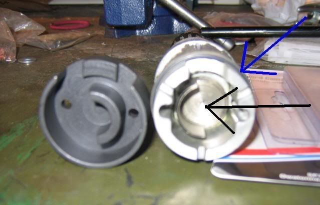
The VR sensor has a single tooth.

-
thewestie
- Experienced MS/Extra'er
- Posts: 201
- Joined: Thu Jan 23, 2014 4:29 pm
- Location: Worcester Ma.
Re: Making cam position sensor for a 351w
Excellent post thank you Laminar.
87 Turbocoupe 351w swap with a TKO, someday a turbo car again.
MS2 3.0 3.4.0
MS2 3.0 3.4.0
Re: Making cam position sensor for a 351w
a few pics of mine, i cut off a 351 shaft and taped the top of it to bolt in a recuctor then copied the 302 housing with 351 bushings
-
thewestie
- Experienced MS/Extra'er
- Posts: 201
- Joined: Thu Jan 23, 2014 4:29 pm
- Location: Worcester Ma.
Re: Making cam position sensor for a 351w
Wow great job. Thanks for the pics Ashford.
87 Turbocoupe 351w swap with a TKO, someday a turbo car again.
MS2 3.0 3.4.0
MS2 3.0 3.4.0
Re: Making cam position sensor for a 351w
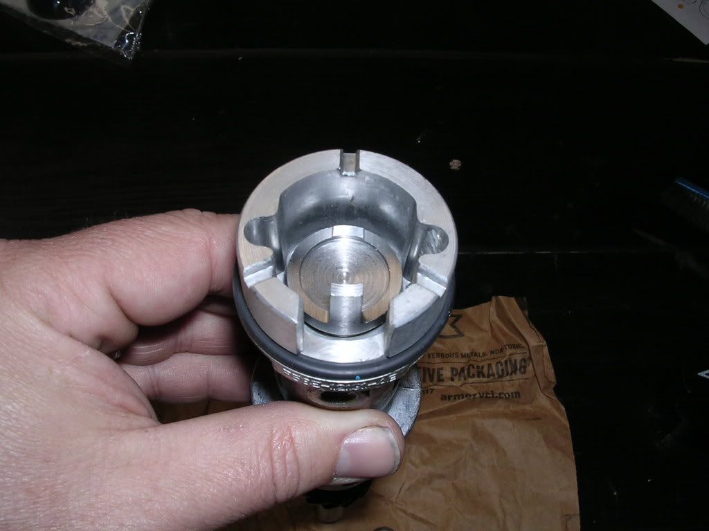
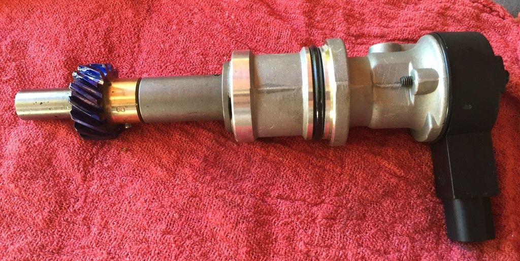
So I dug my parts out to take some pics and illustrate my plan and validate as well  V6 shaft goes in V8 body, done... I think I would like to run the 2 wire sensor so I might try to swap that out too. Just depends on what everything looks like when I pop the caps off. As far as the gear, I am going to run a CompCams 35100 Composite .531" dia. http://www.summitracing.com/parts/cca-35100 as recommended by Comp.
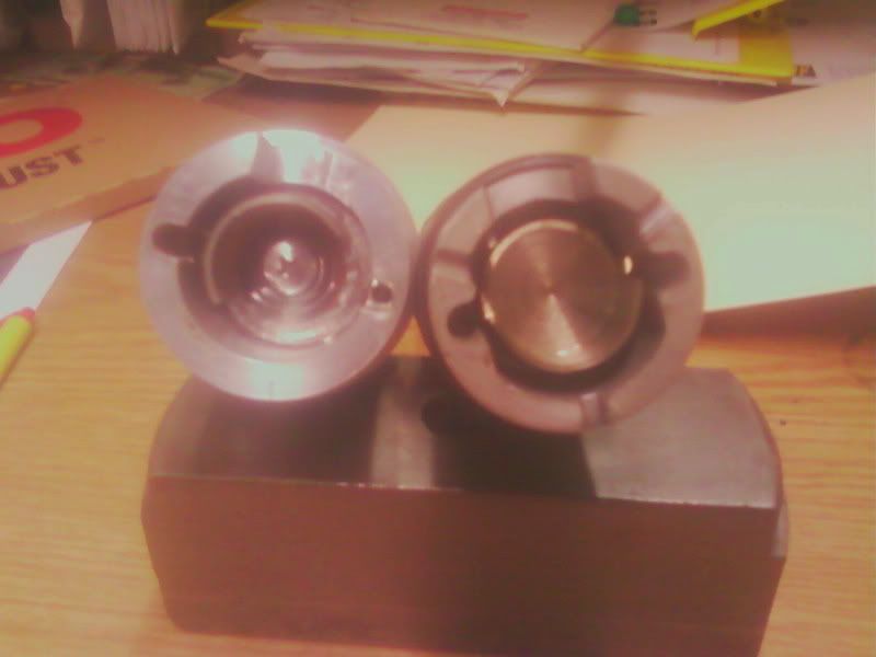
Here are the cam sensors side by side, V8 on the left and V6 on the right.
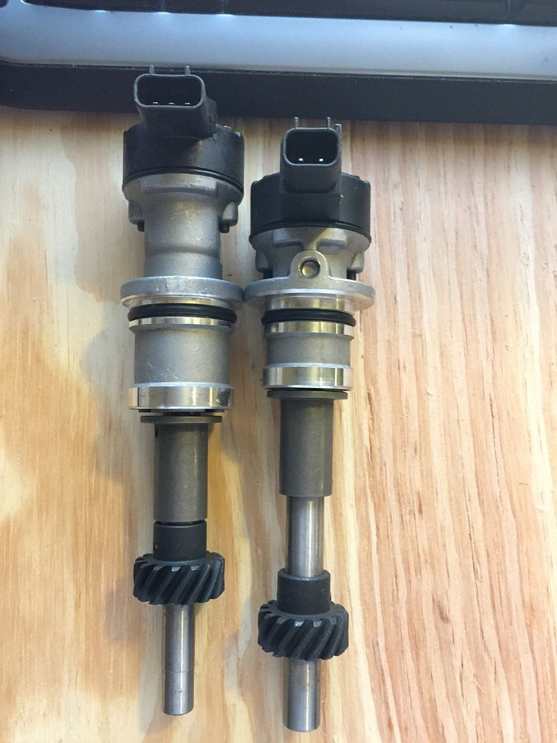
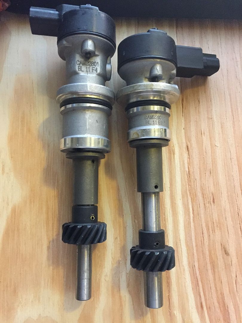
V8 sensor on Ebay http://www.ebay.com/itm/Engine-Camshaft ... 1045392109
V6 sensor on Amazon http://www.amazon.com/Brand-Camshaft-Sy ... B00FSCB248
Here are the cam sensors side by side, V8 on the left and V6 on the right.
V8 sensor on Ebay http://www.ebay.com/itm/Engine-Camshaft ... 1045392109
V6 sensor on Amazon http://www.amazon.com/Brand-Camshaft-Sy ... B00FSCB248
1995 Ford Lightning. Dart based 427 Windsor, Novi 2000, full sequential, E-85, etc. MS3X/v3.57
http://www.buildpics.org/
http://www.buildpics.org/
-
thewestie
- Experienced MS/Extra'er
- Posts: 201
- Joined: Thu Jan 23, 2014 4:29 pm
- Location: Worcester Ma.
Re: Making cam position sensor for a 351w
I have the 3 wire v8 and trying to get the time and the weather to cooperate with me for walking the local yards and search for the v6 and v8 2 wire ones. Keep me posted. I'm interested thanks
87 Turbocoupe 351w swap with a TKO, someday a turbo car again.
MS2 3.0 3.4.0
MS2 3.0 3.4.0
Re: Making cam position sensor for a 351w
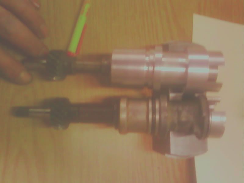
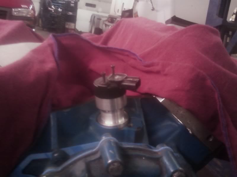
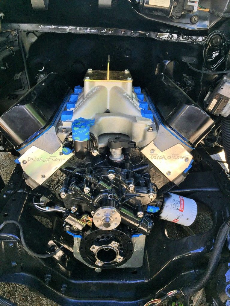
Here's what I ended up with, V-6 drive shaft in V-8 body. This keeps the 2 wire setup. The pic shows a bronze gear installed, I still need to do final measurements then finish drilling the gear and install a new roll pin. I also have Dykem on the gear so I can check the wear pattern.thewestie wrote:I have the 3 wire v8 and trying to get the time and the weather to cooperate with me for walking the local yards and search for the v6 and v8 2 wire ones. Keep me posted. I'm interested thanks
Installed in the engine.
1995 Ford Lightning. Dart based 427 Windsor, Novi 2000, full sequential, E-85, etc. MS3X/v3.57
http://www.buildpics.org/
http://www.buildpics.org/
Re: Making cam position sensor for a 351w
Did you go Hall or VR?
Is the bronze gear compatible with your cam gear?
Does orientation matter? I know for the Ford ECU it has to be installed correctly. I don't know if Megasquirt cares.
Is the bronze gear compatible with your cam gear?
Does orientation matter? I know for the Ford ECU it has to be installed correctly. I don't know if Megasquirt cares.
Re: Making cam position sensor for a 351w
VR, yeah I bought that gear based on Comp Cams recommendation. It was either bronze or composite, and I've seen/heard a lot of stories of the composites failing. I am not excited about running the bronze, I feel it is going to wear rapidly. But I don't want to hurt the cam so I will accept pulling the sensor every so often to check for wear.Laminar wrote:Did you go Hall or VR?
Is the bronze gear compatible with your cam gear?
Does orientation matter? I know for the Ford ECU it has to be installed correctly. I don't know if Megasquirt cares.
That's a good question, I imagine the answer is yes, but I haven't got to the point of getting it sync'd yet. I still have a ton of other stuff to do both electrically and mechanically.
1995 Ford Lightning. Dart based 427 Windsor, Novi 2000, full sequential, E-85, etc. MS3X/v3.57
http://www.buildpics.org/
http://www.buildpics.org/
Re: Making cam position sensor for a 351w
The sound of your oil pump drive shaft falling into the pan is a terrible thing. Be sure you've got the spring washer on the shaft properly so it can't fall out during gear checks. Otherwise......... 
MS2 on Ford 351C, custom internal crank trigger, FAST EZ-EFI TBI, LS truck coils in wasted spark
Re: Making cam position sensor for a 351w
Oh man, I agree 100%! Yes it is all good and safe, so farmustangjp wrote:The sound of your oil pump drive shaft falling into the pan is a terrible thing. Be sure you've got the spring washer on the shaft properly so it can't fall out during gear checks. Otherwise.........
1995 Ford Lightning. Dart based 427 Windsor, Novi 2000, full sequential, E-85, etc. MS3X/v3.57
http://www.buildpics.org/
http://www.buildpics.org/
-
thewestie
- Experienced MS/Extra'er
- Posts: 201
- Joined: Thu Jan 23, 2014 4:29 pm
- Location: Worcester Ma.
Re: Making cam position sensor for a 351w
Raymond_B wrote:Here's what I ended up with, V-6 drive shaft in V-8 body. This keeps the 2 wire setup. The pic shows a bronze gear installed, I still need to do final measurements then finish drilling the gear and install a new roll pin. I also have Dykem on the gear so I can check the wear pattern.thewestie wrote:I have the 3 wire v8 and trying to get the time and the weather to cooperate with me for walking the local yards and search for the v6 and v8 2 wire ones. Keep me posted. I'm interested thanks
Installed in the engine.#
Thanks for the update. It looks so nice. Now I must know how you did the 36-1 wheel and what you did for the pickup. It looks nice.
Thanks
87 Turbocoupe 351w swap with a TKO, someday a turbo car again.
MS2 3.0 3.4.0
MS2 3.0 3.4.0
Re: Making cam position sensor for a 351w
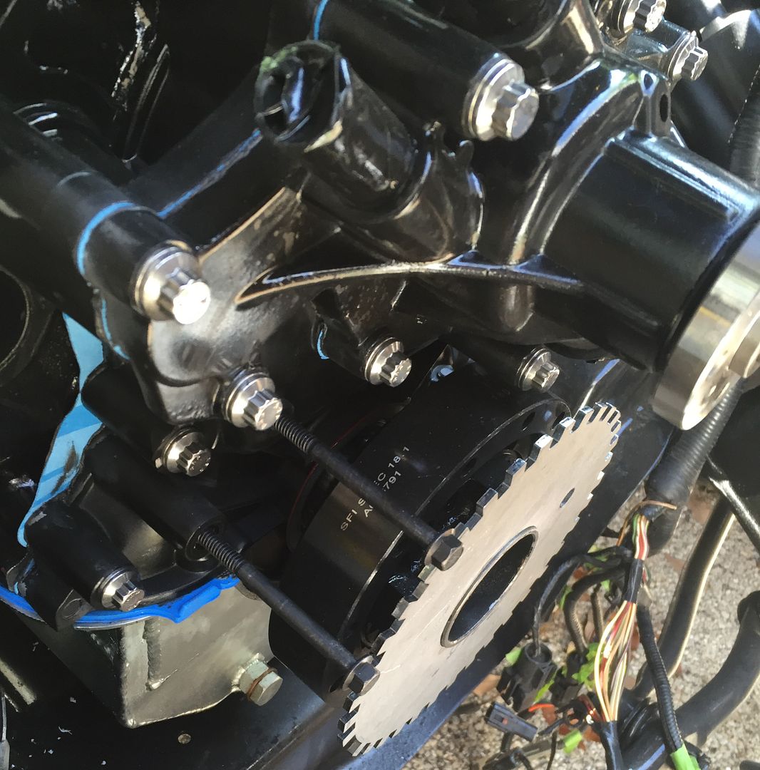
Sorry for the late reply, actually I am working on that now. I decided not to do a bunch of mods to my balancer so I am going to mount the 36-1 wheel between the balancer and the crank pulley. I also think I am going to ditch the stock Ford VR crank sensor and go with a 12v hall effect sensor mounted on a custom bracket. I have a buddy who is an excellent machinist so I am going to ask him to fab that bracket.thewestie wrote:Raymond_B wrote:Here's what I ended up with, V-6 drive shaft in V-8 body. This keeps the 2 wire setup. The pic shows a bronze gear installed, I still need to do final measurements then finish drilling the gear and install a new roll pin. I also have Dykem on the gear so I can check the wear pattern.thewestie wrote:I have the 3 wire v8 and trying to get the time and the weather to cooperate with me for walking the local yards and search for the v6 and v8 2 wire ones. Keep me posted. I'm interested thanks
Thanks for the update. It looks so nice. Now I must know how you did the 36-1 wheel and what you did for the pickup. It looks nice.
Thanks
Here's the wheel in place so I could figure out spacing and mounting options.
1995 Ford Lightning. Dart based 427 Windsor, Novi 2000, full sequential, E-85, etc. MS3X/v3.57
http://www.buildpics.org/
http://www.buildpics.org/
Re: Making cam position sensor for a 351w
Also meant to add, in my search on distributor gear swaps and etc I found this. https://performanceparts.ford.com/downl ... FGHJKL.pdf
Really good info!
Really good info!
1995 Ford Lightning. Dart based 427 Windsor, Novi 2000, full sequential, E-85, etc. MS3X/v3.57
http://www.buildpics.org/
http://www.buildpics.org/
-
whittlebeast
- Super MS/Extra'er
- Posts: 2221
- Joined: Tue May 04, 2004 8:20 pm
- Location: St Louis
- Contact:
Re: Making cam position sensor for a 351w
How does the stock dizzy work? With lots of setups, you can grind all but one of the stock trigger lobes off. You can use the last remaining bump as the cam sensor. I have done this on several installs. As a side note, I did weld the advance plates together so there was no advance going on in the dizzy.
Andy
Andy
Re: Making cam position sensor for a 351w
You can basically do the same thing, but since Ford offered a V-8 cam sensor I decided to go that route (albeit with some modifications for the 351w).
1995 Ford Lightning. Dart based 427 Windsor, Novi 2000, full sequential, E-85, etc. MS3X/v3.57
http://www.buildpics.org/
http://www.buildpics.org/
-
thewestie
- Experienced MS/Extra'er
- Posts: 201
- Joined: Thu Jan 23, 2014 4:29 pm
- Location: Worcester Ma.
Re: Making cam position sensor for a 351w
What are you running for a water pump ? It doesn't look like a fox one.
87 Turbocoupe 351w swap with a TKO, someday a turbo car again.
MS2 3.0 3.4.0
MS2 3.0 3.4.0
Re: Making cam position sensor for a 351w
SN95 pump and timing cover
Sent from my iPhone using Tapatalk
Sent from my iPhone using Tapatalk
1995 Ford Lightning. Dart based 427 Windsor, Novi 2000, full sequential, E-85, etc. MS3X/v3.57
http://www.buildpics.org/
http://www.buildpics.org/
Re: Making cam position sensor for a 351w
I just went through the process of making a 351w sensor by combining an explorer body with a V6 shaft. What nobody mentions is that the distributor hole is larger in the 351w compared to the 302 by about 1/16". Without a sleeve to adapt the explorer cam plug, the O ring won't seal properly and it will be close to impossible to center the plug in the hole.