Yes, using the opto circuit is basically what you have done, but it isolates the input from the MS2 input pin, which can be helpful. Using the opto circuit also provides an easy way to invert the crank signal input, so you dont have to use a transistor on your cam input. This just simplifies things, and provides 2 circuits that are known to work perfectly. It lets you build a very simple pullup circuit for the cam signal, using minimal parts, and has good noise suppression. If you do build the opto circuit, be sure to remove and jumper R12- we dont need a 390 ohm 1/2 watt resistor there.
All the opto is- its a tiny LED that is fired by your input signal, and that triggers a small transistor to provide the 0-5v pulse to the MS2 chip input pin.
It it were me, i would use these wiring input methods, mostly because they work fine for me, and many other wheel setups with hall sensors and 2nd trigger hall sensors use this type of schematic without issue. The opto circuits are already provided for you, so why not keep it simple and proven, by using them? Same goes for the cam input- its as simple as it gets, and works perfectly. Again, just my best suggestion for you, to help eliminate any potential issue with wiring and inputs..gets it out of the equasion.
Can you run the car on the stock computer? This would prove any issues with the 2 sensors not reading correctly.
Having Problems with my MS II
Moderators: jsmcortina, muythaibxr
-
AbeFM
- Super MS/Extra'er
- Posts: 875
- Joined: Wed Dec 05, 2007 1:40 pm
- Location: San Diego, CA
- Contact:
Heh. I've been wondering that. I think the OEM computer does a lot of guessing, and just lived with bad sensor reads in software on starting. Pretty separate from my high RPM deal.
Really, while adjusting the crank sensor still within spec makes sense, I don't see why I should have (or how it would even help) to move my cam sensor further from the wheel.
As you said, the circuit is already there, if I use it I could shave a good 1/4 oz of dead weight from my car. I'll try jumpering it in, but as I see it, I'm replacing something with 100 nanofarads with an equivalent having only 1 nf.
I wonder if it would make sense to swap that cap out?
Really, while adjusting the crank sensor still within spec makes sense, I don't see why I should have (or how it would even help) to move my cam sensor further from the wheel.
As you said, the circuit is already there, if I use it I could shave a good 1/4 oz of dead weight from my car.
I wonder if it would make sense to swap that cap out?
2000 VVT Miata turbo, MS3Pro
Contact me if interested in a MS-II 2nd gen NB Miata PnP board.
Contact me if interested in a MS-II 2nd gen NB Miata PnP board.
-
md95
- Master MS/Extra'er
- Posts: 721
- Joined: Tue Mar 15, 2005 6:44 pm
- Location: Grand Rapids, MI
- Contact:
AbeFM wrote:I'll try jumpering it in, but as I see it, I'm replacing something with 100 nanofarads with an equivalent having only 1 nf.
I wonder if it would make sense to swap that cap out?
You can swap C12 with a .01uf cap to start, and if you still get noise, try a .1uf. I wouldn't go higher than that.
-Matt-
1998 Mitsubishi Eclipse RS 420A Turbo- MS2 Extra- 2.1.0 Release
1992 Plymouth Laser RS 4g63 AWD Turbo MS2 Extra- 3.0.3s
1998 Mitsubishi Eclipse RS 420A Turbo- MS2 Extra- 2.1.0 Release
1992 Plymouth Laser RS 4g63 AWD Turbo MS2 Extra- 3.0.3s
-
AbeFM
- Super MS/Extra'er
- Posts: 875
- Joined: Wed Dec 05, 2007 1:40 pm
- Location: San Diego, CA
- Contact:
From the PCBv3 schematic:
What do you think?

This makes it sound like you'd put +5V on OptoIn (or D2, like you said) and jumper XG1 right to TachSelect, and leave everything else in the circuit. Then it'll have quite a bit of capacitance, and be waiting for an external HALL to ground it. It won't invert but I don't care, I can invert my cam signal.Note 4: Jumper locations XG1 and XG2 normally jumpered. For extreme ignition coil noise, XG1 can be grounded
directly to engine via external connection. XG1 can also be used for Hall sensor open-collector operation.
What do you think?
2000 VVT Miata turbo, MS3Pro
Contact me if interested in a MS-II 2nd gen NB Miata PnP board.
Contact me if interested in a MS-II 2nd gen NB Miata PnP board.
-
md95
- Master MS/Extra'er
- Posts: 721
- Joined: Tue Mar 15, 2005 6:44 pm
- Location: Grand Rapids, MI
- Contact:
Use the diagram that was posted, taking note of how i said to do it. You dont want to use TOO much capacitance, as it can effect the input signal or even cause a time delay. You dont want any more than a total of .1uf. Thats plenty enough, even provides headroom.AbeFM wrote:From the PCBv3 schematic:This makes it sound like you'd put +5V on OptoIn (or D2, like you said) and jumper XG1 right to TachSelect, and leave everything else in the circuit. Then it'll have quite a bit of capacitance, and be waiting for an external HALL to ground it. It won't invert but I don't care, I can invert my cam signal.Note 4: Jumper locations XG1 and XG2 normally jumpered. For extreme ignition coil noise, XG1 can be grounded
directly to engine via external connection. XG1 can also be used for Hall sensor open-collector operation.
What do you think?
Using the opto circuit like you said, is a waste..since you still have to invert your cam signal! It makes no sense to do it that way. Keep it simple!
-Matt-
1998 Mitsubishi Eclipse RS 420A Turbo- MS2 Extra- 2.1.0 Release
1992 Plymouth Laser RS 4g63 AWD Turbo MS2 Extra- 3.0.3s
1998 Mitsubishi Eclipse RS 420A Turbo- MS2 Extra- 2.1.0 Release
1992 Plymouth Laser RS 4g63 AWD Turbo MS2 Extra- 3.0.3s
-
AbeFM
- Super MS/Extra'er
- Posts: 875
- Joined: Wed Dec 05, 2007 1:40 pm
- Location: San Diego, CA
- Contact:
Ok, in looking more closely, it appears I jumped to conclusions. Your suggested circuit and mine are identical:

Basically, the main difference is the extra cap. I've got a few less ohms (easy enough to bump up).
Is my logic off here? See if you think the circuit goes the same way...
The cap I'm not SO worried about, since looking on the scope I never saw rounded corners. Maybe I'll go look harder for them! That could definitely be my whole issue. It sure seems I'm just missing the occasional rising edge (there's a %error spec I've noticed, and if I could log much faster I'd have a LOT more info there.)
2000 VVT Miata turbo, MS3Pro
Contact me if interested in a MS-II 2nd gen NB Miata PnP board.
Contact me if interested in a MS-II 2nd gen NB Miata PnP board.
-
md95
- Master MS/Extra'er
- Posts: 721
- Joined: Tue Mar 15, 2005 6:44 pm
- Location: Grand Rapids, MI
- Contact:
Your "as suggested" diagram is not what i was saying for the opto input for the crank signal. You want to jump XG1 to XG2, to provide the ground on one side of the opto's input. Then, use a 470 ohm pullup to opto in, and you can jumper D1 and D2, remove and jump R12, remove C30, and use a .01uf cap for C12. This inverts the crank signal. Then use the simple pullup circuit with a .1uf cap for you cam signal. Thats it.
-Matt-
1998 Mitsubishi Eclipse RS 420A Turbo- MS2 Extra- 2.1.0 Release
1992 Plymouth Laser RS 4g63 AWD Turbo MS2 Extra- 3.0.3s
1998 Mitsubishi Eclipse RS 420A Turbo- MS2 Extra- 2.1.0 Release
1992 Plymouth Laser RS 4g63 AWD Turbo MS2 Extra- 3.0.3s
Here's a summary of where I'm at right now. This is a PM I sent to arga.
Twice I've been told I should talk to arga on mt.net, so here it goes.
I have a few questions for you about my MS II. I built a V3.0 MS II. I have a MegaStim V2.21. I have the latest MS II extra beta code, b18.
I skipped steps 50, 51, and 52 on the assembly instructions(AbeFM said to skip them) for MS, since they are for ignition inputs and I have custom input circuits. I'll attach a picture of the schematics I'm running for ignition. The schematics are what AbeFM said to build. He says they are similar to what he's running, but that my version has a couple extra resistors.
I can't get a RPM or O2 signal from my stim to show on Megatune. It never syncs, no RPM readings. I've installed MS on the car and the same thing, no RPM signal and no sync. I adjusted the hall effect crank sensor to .020" from the teeth to wheel. It still showed nothing on MT.
In Megatune, I changed spark mode from miata 99-00 to basic, and I got a good RPM reading on my RPM guage in MT, the fuel injector guage was moving, and the outer LEDs on the MS II were flashing. It never cranked though. I'm only letting MS run fuel right now, the stock ecu is doing everything but fuel.
I also tried shimming my Cam Position Sensor as AbeFM suggested. I tried it at stock, .020, .040, and .065. When I adjusted the CPS, it still didn't sync using 99-00 miata. I changed it to basic, and it was reading half of what it used to read when I spinned it over. It was 290 RPM, and with the CPS shimmed, it was 130-140.
If I apply ground to pin TSEL, MegaTune will respond and I'll get a random signal on the RPM guage. The faster I tap ground, the higher the guage climbs.
I'm not sure what I should do next. It may be something simple and I hope it is, but I'm lost and don't know where to go from here. Just looking at pictures of AbeFM's MS II, it has a lot more components installed then mine. He said to skip steps 50,51,and 52, but his MS II seems to have a lot of those components. Chad Jernigan suggest I should install them anyway, although they shouldn't do anything.
the cam sensor signal coming in on pin 25, IAC1A. I have a wire going from IAC1A to the input of my cam circuit. It goes out of the cam circuit and goes to JS10.
slomx5 (9:50:20 PM): The crank sensor signal comes in on pin 24, Tachselect. I have a wire going from tachselect to the input of my crank circuit. It goes out of the cam circuit and goes to TSEL.
I have wires going from the outer LEDs on MS going to IAC2B and IGN. Those are the only wires on my board. There are no other jumpers.
My board does not have the following components:
U3, U7, Resistors52,55,42,54,53,56,44,50,49,47,51,57,13,45,46,12,49,43,)
Capacitors(12,30,32,31,11)
Diodes(1,2,24,8,
transistors(20,16)
Here's a link to a thread I started on the MSExtra forums:
http://www.msextra.com/viewtopic.php?t= ... sc&start=0
Here's a link to the schematics I followed to build my input circuits for the ignition:
http://abefm.smugmug.com/gallery/4071849#242249921-A-LB
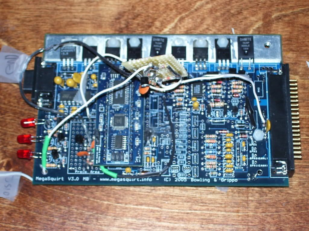
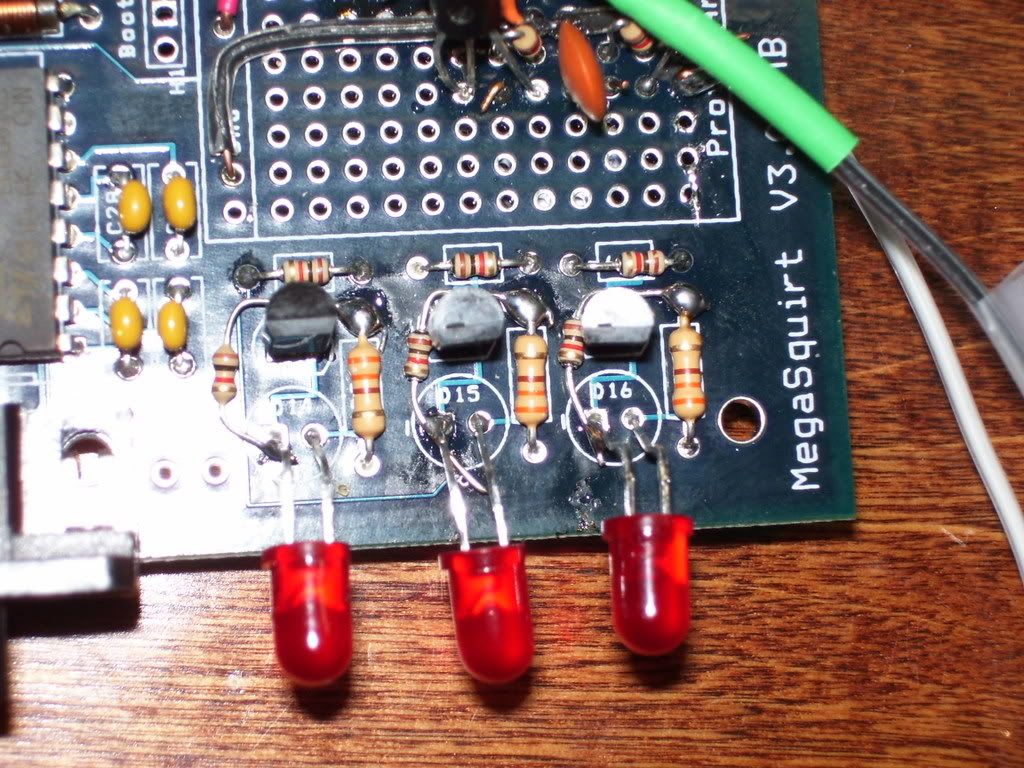
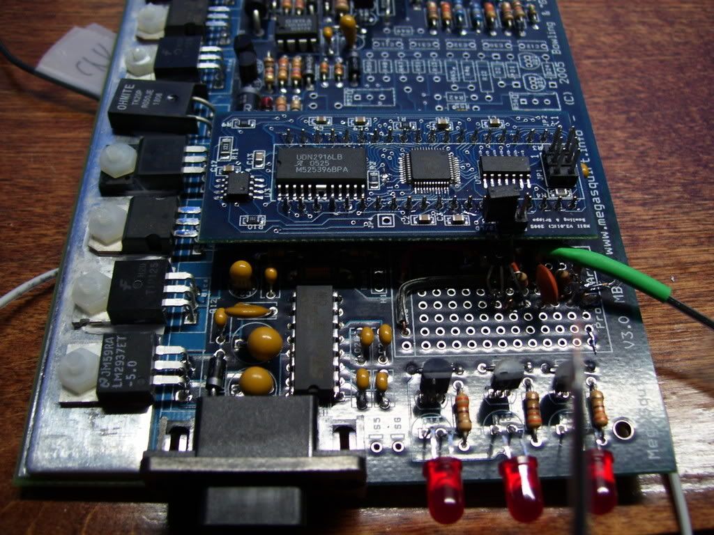
Here's a few pictures of my MSII.
http://i231.photobucket.com/albums/ee15 ... MSPic8.jpg
http://i231.photobucket.com/albums/ee15 ... MSPic4.jpg
http://i231.photobucket.com/albums/ee15 ... MSPic3.jpg
Thanks in advance for any and all help.
Patrick.
Twice I've been told I should talk to arga on mt.net, so here it goes.
I have a few questions for you about my MS II. I built a V3.0 MS II. I have a MegaStim V2.21. I have the latest MS II extra beta code, b18.
I skipped steps 50, 51, and 52 on the assembly instructions(AbeFM said to skip them) for MS, since they are for ignition inputs and I have custom input circuits. I'll attach a picture of the schematics I'm running for ignition. The schematics are what AbeFM said to build. He says they are similar to what he's running, but that my version has a couple extra resistors.
I can't get a RPM or O2 signal from my stim to show on Megatune. It never syncs, no RPM readings. I've installed MS on the car and the same thing, no RPM signal and no sync. I adjusted the hall effect crank sensor to .020" from the teeth to wheel. It still showed nothing on MT.
In Megatune, I changed spark mode from miata 99-00 to basic, and I got a good RPM reading on my RPM guage in MT, the fuel injector guage was moving, and the outer LEDs on the MS II were flashing. It never cranked though. I'm only letting MS run fuel right now, the stock ecu is doing everything but fuel.
I also tried shimming my Cam Position Sensor as AbeFM suggested. I tried it at stock, .020, .040, and .065. When I adjusted the CPS, it still didn't sync using 99-00 miata. I changed it to basic, and it was reading half of what it used to read when I spinned it over. It was 290 RPM, and with the CPS shimmed, it was 130-140.
If I apply ground to pin TSEL, MegaTune will respond and I'll get a random signal on the RPM guage. The faster I tap ground, the higher the guage climbs.
I'm not sure what I should do next. It may be something simple and I hope it is, but I'm lost and don't know where to go from here. Just looking at pictures of AbeFM's MS II, it has a lot more components installed then mine. He said to skip steps 50,51,and 52, but his MS II seems to have a lot of those components. Chad Jernigan suggest I should install them anyway, although they shouldn't do anything.
the cam sensor signal coming in on pin 25, IAC1A. I have a wire going from IAC1A to the input of my cam circuit. It goes out of the cam circuit and goes to JS10.
slomx5 (9:50:20 PM): The crank sensor signal comes in on pin 24, Tachselect. I have a wire going from tachselect to the input of my crank circuit. It goes out of the cam circuit and goes to TSEL.
I have wires going from the outer LEDs on MS going to IAC2B and IGN. Those are the only wires on my board. There are no other jumpers.
My board does not have the following components:
U3, U7, Resistors52,55,42,54,53,56,44,50,49,47,51,57,13,45,46,12,49,43,)
Capacitors(12,30,32,31,11)
Diodes(1,2,24,8,
transistors(20,16)
Here's a link to a thread I started on the MSExtra forums:
http://www.msextra.com/viewtopic.php?t= ... sc&start=0
Here's a link to the schematics I followed to build my input circuits for the ignition:
http://abefm.smugmug.com/gallery/4071849#242249921-A-LB
Here's a few pictures of my MSII.
http://i231.photobucket.com/albums/ee15 ... MSPic8.jpg
http://i231.photobucket.com/albums/ee15 ... MSPic4.jpg
http://i231.photobucket.com/albums/ee15 ... MSPic3.jpg
Thanks in advance for any and all help.
Patrick.
Here's a summary of where I'm at right now. This is a PM I sent to arga.
Twice I've been told I should talk to arga on mt.net, so here it goes.
I have a few questions for you about my MS II. I built a V3.0 MS II. I have a MegaStim V2.21. I have the latest MS II extra beta code, b18.
I skipped steps 50, 51, and 52 on the assembly instructions(AbeFM said to skip them) for MS, since they are for ignition inputs and I have custom input circuits. I'll attach a picture of the schematics I'm running for ignition. The schematics are what AbeFM said to build. He says they are similar to what he's running, but that my version has a couple extra resistors.
I can't get a RPM or O2 signal from my stim to show on Megatune. It never syncs, no RPM readings. I've installed MS on the car and the same thing, no RPM signal and no sync. I adjusted the hall effect crank sensor to .020" from the teeth to wheel. It still showed nothing on MT.
In Megatune, I changed spark mode from miata 99-00 to basic, and I got a good RPM reading on my RPM guage in MT, the fuel injector guage was moving, and the outer LEDs on the MS II were flashing. It never cranked though. I'm only letting MS run fuel right now, the stock ecu is doing everything but fuel.
I also tried shimming my Cam Position Sensor as AbeFM suggested. I tried it at stock, .020, .040, and .065. When I adjusted the CPS, it still didn't sync using 99-00 miata. I changed it to basic, and it was reading half of what it used to read when I spinned it over. It was 290 RPM, and with the CPS shimmed, it was 130-140.
If I apply ground to pin TSEL, MegaTune will respond and I'll get a random signal on the RPM guage. The faster I tap ground, the higher the guage climbs.
I'm not sure what I should do next. It may be something simple and I hope it is, but I'm lost and don't know where to go from here. Just looking at pictures of AbeFM's MS II, it has a lot more components installed then mine. He said to skip steps 50,51,and 52, but his MS II seems to have a lot of those components. Chad Jernigan suggest I should install them anyway, although they shouldn't do anything.
the cam sensor signal coming in on pin 25, IAC1A. I have a wire going from IAC1A to the input of my cam circuit. It goes out of the cam circuit and goes to JS10.
slomx5 (9:50:20 PM): The crank sensor signal comes in on pin 24, Tachselect. I have a wire going from tachselect to the input of my crank circuit. It goes out of the cam circuit and goes to TSEL.
I have wires going from the outer LEDs on MS going to IAC2B and IGN. Those are the only wires on my board. There are no other jumpers.
My board does not have the following components:
U3, U7, Resistors52,55,42,54,53,56,44,50,49,47,51,57,13,45,46,12,49,43,)
Capacitors(12,30,32,31,11)
Diodes(1,2,24,8,
transistors(20,16)
Here's a link to a thread I started on the MSExtra forums:
http://www.msextra.com/viewtopic.php?t= ... sc&start=0
Here's a link to the schematics I followed to build my input circuits for the ignition:
http://abefm.smugmug.com/gallery/4071849#242249921-A-LB
Here's a few pictures of my MSII.
http://i231.photobucket.com/albums/ee15 ... MSPic8.jpg
http://i231.photobucket.com/albums/ee15 ... MSPic4.jpg
http://i231.photobucket.com/albums/ee15 ... MSPic3.jpg
Thanks in advance for any and all help.
Patrick.
hey
Here's a summary of where I'm at right now. This is a PM I sent to arga.
Twice I've been told I should talk to arga on mt.net, so here it goes.
I have a few questions for you about my MS II. I built a V3.0 MS II. I have a MegaStim V2.21. I have the latest MS II extra beta code, b18.
I skipped steps 50, 51, and 52 on the assembly instructions(AbeFM said to skip them) for MS, since they are for ignition inputs and I have custom input circuits. I'll attach a picture of the schematics I'm running for ignition. The schematics are what AbeFM said to build. He says they are similar to what he's running, but that my version has a couple extra resistors.
I can't get a RPM or O2 signal from my stim to show on Megatune. It never syncs, no RPM readings. I've installed MS on the car and the same thing, no RPM signal and no sync. I adjusted the hall effect crank sensor to .020" from the teeth to wheel. It still showed nothing on MT.
In Megatune, I changed spark mode from miata 99-00 to basic, and I got a good RPM reading on my RPM guage in MT, the fuel injector guage was moving, and the outer LEDs on the MS II were flashing. It never cranked though. I'm only letting MS run fuel right now, the stock ecu is doing everything but fuel.
I also tried shimming my Cam Position Sensor as AbeFM suggested. I tried it at stock, .020, .040, and .065. When I adjusted the CPS, it still didn't sync using 99-00 miata. I changed it to basic, and it was reading half of what it used to read when I spinned it over. It was 290 RPM, and with the CPS shimmed, it was 130-140.
If I apply ground to pin TSEL, MegaTune will respond and I'll get a random signal on the RPM guage. The faster I tap ground, the higher the guage climbs.
I'm not sure what I should do next. It may be something simple and I hope it is, but I'm lost and don't know where to go from here. Just looking at pictures of AbeFM's MS II, it has a lot more components installed then mine. He said to skip steps 50,51,and 52, but his MS II seems to have a lot of those components. Chad Jernigan suggest I should install them anyway, although they shouldn't do anything.
the cam sensor signal coming in on pin 25, IAC1A. I have a wire going from IAC1A to the input of my cam circuit. It goes out of the cam circuit and goes to JS10.
slomx5 (9:50:20 PM): The crank sensor signal comes in on pin 24, Tachselect. I have a wire going from tachselect to the input of my crank circuit. It goes out of the cam circuit and goes to TSEL.
I have wires going from the outer LEDs on MS going to IAC2B and IGN. Those are the only wires on my board. There are no other jumpers.
My board does not have the following components:
U3, U7, Resistors52,55,42,54,53,56,44,50,49,47,51,57,13,45,46,12,49,43,)
Capacitors(12,30,32,31,11)
Diodes(1,2,24,8,
transistors(20,16)
Here's a link to a thread I started on the MSExtra forums:
http://www.msextra.com/viewtopic.php?t= ... sc&start=0
Here's a link to the schematics I followed to build my input circuits for the ignition:
http://abefm.smugmug.com/gallery/4071849#242249921-A-LB
Here's a few pictures of my MSII.
http://i231.photobucket.com/albums/ee15 ... MSPic8.jpg
http://i231.photobucket.com/albums/ee15 ... MSPic4.jpg
http://i231.photobucket.com/albums/ee15 ... MSPic3.jpg
Thanks in advance for any and all help.
Patrick.
Twice I've been told I should talk to arga on mt.net, so here it goes.
I have a few questions for you about my MS II. I built a V3.0 MS II. I have a MegaStim V2.21. I have the latest MS II extra beta code, b18.
I skipped steps 50, 51, and 52 on the assembly instructions(AbeFM said to skip them) for MS, since they are for ignition inputs and I have custom input circuits. I'll attach a picture of the schematics I'm running for ignition. The schematics are what AbeFM said to build. He says they are similar to what he's running, but that my version has a couple extra resistors.
I can't get a RPM or O2 signal from my stim to show on Megatune. It never syncs, no RPM readings. I've installed MS on the car and the same thing, no RPM signal and no sync. I adjusted the hall effect crank sensor to .020" from the teeth to wheel. It still showed nothing on MT.
In Megatune, I changed spark mode from miata 99-00 to basic, and I got a good RPM reading on my RPM guage in MT, the fuel injector guage was moving, and the outer LEDs on the MS II were flashing. It never cranked though. I'm only letting MS run fuel right now, the stock ecu is doing everything but fuel.
I also tried shimming my Cam Position Sensor as AbeFM suggested. I tried it at stock, .020, .040, and .065. When I adjusted the CPS, it still didn't sync using 99-00 miata. I changed it to basic, and it was reading half of what it used to read when I spinned it over. It was 290 RPM, and with the CPS shimmed, it was 130-140.
If I apply ground to pin TSEL, MegaTune will respond and I'll get a random signal on the RPM guage. The faster I tap ground, the higher the guage climbs.
I'm not sure what I should do next. It may be something simple and I hope it is, but I'm lost and don't know where to go from here. Just looking at pictures of AbeFM's MS II, it has a lot more components installed then mine. He said to skip steps 50,51,and 52, but his MS II seems to have a lot of those components. Chad Jernigan suggest I should install them anyway, although they shouldn't do anything.
the cam sensor signal coming in on pin 25, IAC1A. I have a wire going from IAC1A to the input of my cam circuit. It goes out of the cam circuit and goes to JS10.
slomx5 (9:50:20 PM): The crank sensor signal comes in on pin 24, Tachselect. I have a wire going from tachselect to the input of my crank circuit. It goes out of the cam circuit and goes to TSEL.
I have wires going from the outer LEDs on MS going to IAC2B and IGN. Those are the only wires on my board. There are no other jumpers.
My board does not have the following components:
U3, U7, Resistors52,55,42,54,53,56,44,50,49,47,51,57,13,45,46,12,49,43,)
Capacitors(12,30,32,31,11)
Diodes(1,2,24,8,
transistors(20,16)
Here's a link to a thread I started on the MSExtra forums:
http://www.msextra.com/viewtopic.php?t= ... sc&start=0
Here's a link to the schematics I followed to build my input circuits for the ignition:
http://abefm.smugmug.com/gallery/4071849#242249921-A-LB
Here's a few pictures of my MSII.
http://i231.photobucket.com/albums/ee15 ... MSPic8.jpg
http://i231.photobucket.com/albums/ee15 ... MSPic4.jpg
http://i231.photobucket.com/albums/ee15 ... MSPic3.jpg
Thanks in advance for any and all help.
Patrick.
-
AbeFM
- Super MS/Extra'er
- Posts: 875
- Joined: Wed Dec 05, 2007 1:40 pm
- Location: San Diego, CA
- Contact:
At this point, I don't have a lot to do but try it - I guess I read it the first time and second just looked at the posted pic. Sorry for the confusion.md95 wrote:Your "as suggested" diagram is not what i was saying for the opto input for the crank signal. You want to jump XG1 to XG2, to provide the ground on one side of the opto's input. Then, use a 470 ohm pullup to opto in, and you can jumper D1 and D2, remove and jump R12, remove C30, and use a .01uf cap for C12. This inverts the crank signal. Then use the simple pullup circuit with a .1uf cap for you cam signal. Thats it.
Truely, the way you're saying to use it seems (to me) to be exactly what I'm already using on my can, a NPN follower. The neon circuit (like what I drew, too) uses the grounding of the sensor in a different way. I guess the real point is anything that's resistant to noise should help. I'll try to watch the rise rates of the pulses next time I get my hands on a scope. At least moving wires around is pretty easy, it's nice B&G put all those jumpers in.
2000 VVT Miata turbo, MS3Pro
Contact me if interested in a MS-II 2nd gen NB Miata PnP board.
Contact me if interested in a MS-II 2nd gen NB Miata PnP board.
-
md95
- Master MS/Extra'er
- Posts: 721
- Joined: Tue Mar 15, 2005 6:44 pm
- Location: Grand Rapids, MI
- Contact:
This is the schemaitc, a bit crude with MS paint, but you get the idea.
http://www.geocities.com/mitsurst95/Pic ... input1.JPG
http://www.geocities.com/mitsurst95/Pic ... input1.JPG
-Matt-
1998 Mitsubishi Eclipse RS 420A Turbo- MS2 Extra- 2.1.0 Release
1992 Plymouth Laser RS 4g63 AWD Turbo MS2 Extra- 3.0.3s
1998 Mitsubishi Eclipse RS 420A Turbo- MS2 Extra- 2.1.0 Release
1992 Plymouth Laser RS 4g63 AWD Turbo MS2 Extra- 3.0.3s
-
jsmcortina
- Site Admin
- Posts: 39621
- Joined: Mon May 03, 2004 1:34 am
- Location: Birmingham, UK
- Contact:
I can repair or upgrade Megasquirts in UK. http://www.jamesmurrayengineering.co.uk
My Success story: http://www.msextra.com/forums/viewtopic ... 04&t=34277
MSEXTRA documentation at: http://www.msextra.com/doc/index.html
New users, please read the "Forum Help Page".
My Success story: http://www.msextra.com/forums/viewtopic ... 04&t=34277
MSEXTRA documentation at: http://www.msextra.com/doc/index.html
New users, please read the "Forum Help Page".
-
md95
- Master MS/Extra'er
- Posts: 721
- Joined: Tue Mar 15, 2005 6:44 pm
- Location: Grand Rapids, MI
- Contact:
Ah exactly what I've been looking for! Thanks James.jsmcortina wrote:OT: For drawing schems you could try Eagle - there's a free download via www.cadsoft.de
James
-Matt-
1998 Mitsubishi Eclipse RS 420A Turbo- MS2 Extra- 2.1.0 Release
1992 Plymouth Laser RS 4g63 AWD Turbo MS2 Extra- 3.0.3s
1998 Mitsubishi Eclipse RS 420A Turbo- MS2 Extra- 2.1.0 Release
1992 Plymouth Laser RS 4g63 AWD Turbo MS2 Extra- 3.0.3s