robs,
I studied your noisy signal again in your first post.
Are the spikes one sample wide? Or are they sometimes 2 samples wide? (at 10 ms samping rate)
I studied your moving anchor algorithm. It is simply a nonlinear filter that sets the TPSdot to zero if the TPS has not changed by TPS_eps amount.
This is no different than the TPSdot threshold in the AEM. That is, it won't add any enrichment below a certain TPSdot threshold. This is de rigeur.
The best algorithm IMO like I said earlier, is a combo of a 2-pole analog RC filter, a 2-pole IIR ("lag") filter, then the threshold settings (which you call the "moving anchor"). I suspect having the moving anchor after the lag filter is better than having it before.
Again if the ramp delay time (which translates to the rise time of TPSdot), needs to be 20-30 ms and the sampling rate is 10 ms, then the lag factor needs to be 50% for a 1-pole filter, and 70% for a 2-pole.
Looking at your pdf's:
If the sampling rate is 10 ms and the desired ramp delay time is 20-30 ms then the 2-pole Bessel is only a little better than a 1-pole filter. The 2-pole filter gets better at higher sampling rates, i.e. the acceptable ramp delay time is longer in terms of # of samples.
This is why I suggested 5 ms sampling for TPS in an earlier post, if ramp delay times need to be < 30 ms. (ramp delay time = 6 samples)
If sampling rate is increased, then the 2 pole filter will show better attenuation of high frequency noise, such as
0 1 0 1 0 1
or an impulse
0 1 0 0 0 0
"Noisy" tpsDOT
Moderators: jsmcortina, muythaibxr
-
JasonC SBB
- Helpful MS/Extra'er
- Posts: 120
- Joined: Wed Oct 26, 2011 7:36 pm
Re: "Noisy" tpsDOT
Last edited by JasonC SBB on Wed Feb 22, 2012 3:14 pm, edited 2 times in total.
-
JasonC SBB
- Helpful MS/Extra'er
- Posts: 120
- Joined: Wed Oct 26, 2011 7:36 pm
Re: "Noisy" tpsDOT
I was writing using the standard filters lingo in case any readers are familiar with it (because it reduces mis interpretation when I type it, and if I try to show pseudocode that I can't test, I will likely make logical errors).robs wrote:Indeed it is a matter of lingo. I am very happy for you to think in whatever terms you find useful, but when it comes to expressing your thoughts you should consider your audience. It has really been pretty hard work for me to turn the terms of "control systems, signals and analog filters" into their code equivalents. Considering you're advocating implementing this filter in particular as code, would it not be reasonable to describe things a little less oracularly?
-
jsmcortina
- Site Admin
- Posts: 39617
- Joined: Mon May 03, 2004 1:34 am
- Location: Birmingham, UK
- Contact:
Re: "Noisy" tpsDOT
In a later post Rob mentioned that he thought these could be due to the code restarting the ADC conversion sequence. I've studied the code and I'm inclined to agree that the code there could cause a problem. It is only a tiny code change and as yet untested.JasonC SBB wrote:robs,
I studied your noisy signal again in your first post.
Are the spikes one sample wide
James
I can repair or upgrade Megasquirts in UK. http://www.jamesmurrayengineering.co.uk
My Success story: http://www.msextra.com/forums/viewtopic ... 04&t=34277
MSEXTRA documentation at: http://www.msextra.com/doc/index.html
New users, please read the "Forum Help Page".
My Success story: http://www.msextra.com/forums/viewtopic ... 04&t=34277
MSEXTRA documentation at: http://www.msextra.com/doc/index.html
New users, please read the "Forum Help Page".
-
JasonC SBB
- Helpful MS/Extra'er
- Posts: 120
- Joined: Wed Oct 26, 2011 7:36 pm
Re: "Noisy" tpsDOT
robs,
I studied you moving anchor results and something I'm puzzled about, is why does it have no delay in detecting the beginning and end of the ramp. Attached shows my question. The way I understand it, it seems to me there should be a delay after the ramp begins, before TPS_EPS is exceeded, which translates to a delay before the dot output sees the slope.
I studied you moving anchor results and something I'm puzzled about, is why does it have no delay in detecting the beginning and end of the ramp. Attached shows my question. The way I understand it, it seems to me there should be a delay after the ramp begins, before TPS_EPS is exceeded, which translates to a delay before the dot output sees the slope.
Re: "Noisy" tpsDOT
You're referring to the very rare spikes I would see in mapDOT. Jason's talking about the much more frequent spikes in TPS that sparked this thread. They largely disappeared when I fixed up a bad connector in the loom (on the ground wire from the TPS), but the thread lives on...jsmcortina wrote: In a later post Rob mentioned that he thought these could be due to the code restarting the ADC conversion sequence. I've studied the code and I'm inclined to agree that the code there could cause a problem. It is only a tiny code change and as yet untested.
Have fun,
Rob.
-
gslender
- Super MS/Extra'er
- Posts: 1072
- Joined: Fri Sep 16, 2011 5:29 am
- Location: Brisbane, Australia
- Contact:
Re: "Noisy" tpsDOT
You are right. It's response is delayed, just that he's suggesting the slope isn't.JasonC SBB wrote:robs,
I studied you moving anchor results and something I'm puzzled about, is why does it have no delay in detecting the beginning and end of the ramp. Attached shows my question. The way I understand it, it seems to me there should be a delay after the ramp begins, before TPS_EPS is exceeded, which translates to a delay before the dot output sees the slope.
It would be more saw tooth than he's showing.
G
Mazda MX5 + MS3 Pro
-
JasonC SBB
- Helpful MS/Extra'er
- Posts: 120
- Joined: Wed Oct 26, 2011 7:36 pm
Re: "Noisy" tpsDOT
So it's no better in regards to the tradeoff between reaction time vs. noise rejection, than say, the 2-pole filter.
My conclusions are:
- correct your ground wiring
- add the 2-pole RCRC filter I suggest (be sure to pick the correct values to get the desired ramp delay time)
- IF the ramp delay time really needs to be in the range of 20-30 ms, then increase TPS sampling rate to 5 ms / 200 Hz.
--- this allows the 2-pole Bessel filter to be more effective
- use a software 2-pole Bessel with a ramp delay time of 20-30 ms
- also implement a minimum threshold for TPSdot, below which there is no acceleration enrichment
Later perhaps create a model of MAP for a given TPS vs RPM and use that for the enrichment algorithm, instead of simply using tables driven by TPSdot. (See Adaptronic tuning software).
-
jsmcortina
- Site Admin
- Posts: 39617
- Joined: Mon May 03, 2004 1:34 am
- Location: Birmingham, UK
- Contact:
Re: "Noisy" tpsDOT
This has been in the code since day 1.JasonC SBB wrote:- also implement a minimum threshold for TPSdot, below which there is no acceleration enrichment
James
I can repair or upgrade Megasquirts in UK. http://www.jamesmurrayengineering.co.uk
My Success story: http://www.msextra.com/forums/viewtopic ... 04&t=34277
MSEXTRA documentation at: http://www.msextra.com/doc/index.html
New users, please read the "Forum Help Page".
My Success story: http://www.msextra.com/forums/viewtopic ... 04&t=34277
MSEXTRA documentation at: http://www.msextra.com/doc/index.html
New users, please read the "Forum Help Page".
Re: "Noisy" tpsDOT
Quite a few postings there Jason.
Happy birthday for yesterday.
It looks like you've been rereading the thread from the start. A good idea, but it may confuse a few people talking about the reduced sampling rate, which was my first stab at getting the noise under control. The moving anchor approach has brought this back up to 100 samples per second. One point. My own memory from back then is a bit vague, but where you explain:
Interestingly enough though, the latest thoughts are to move back towards changing the sampling rate again, taking the mean of a burst of samples at some select point(s) in the injection cycle. Intuitively, no matter how accurately you measure throttle movements, you can't do much about it before the next squirt, and this "just fast enough" sampling should greatly reduce inaccuracy in tpsDOT values, particularly at slow engine speeds.
Thanks for the explanation of some other ECU's approaches to TPS handling. I was just going on the basic geometry that the butterfly presents in the throttle body to see that it must be nonlinear. Potentially, this could have been corrected for in the TPS itself, but I thought this unlikely. Anyhow, it makes perfect sense that a combination of TPS and RPM can be calibrated to model cylinder filling more like an AFM. Seems like this sort of setup could get by without a MAP sensor (but would need baro), or does the MAP come in handy for accel enrichment; kind of the complement of MS where MAP is the main metering input, only using TPS to augment.
Interesting stuff to mull over.
BTW, you keep referring to AEM. I'd never heard of them (but that's no great surprise). Googled them up quickly. Decent value on the surface, but they look to be taking quite a different path from MS. Just wondering where your interest in Megasquirt fits in.
I started this thread because noise on my TPS had suddenly become a problem. Being the proverbial "man with a hammer", I went to the code to see what could be done, and this has been interesting and, at least for my car, helpful. But a month or so ago I tracked down a loose spade connector in the loom which was the source of the new noise.
A nonlinear filter that simply leaves tpsDOT with its current value unless the TPS has either (1) moved from its previous change point by at least TPS_eps; or (2) not moved by this much for TPS_persist samples. In case (1), tpsDOT is set to the average rate of change of TPS since the last change point. In case (2) tpsDOT is set to zero. In either case, the latest sample is set down as the latest change point.
This has two obvious drawbacks: a delay in noticing real movements due to the threshold value (no biggie); tpsDOT living on beyond actual TPS movement for TPS_persist samples before we decide that accel is no longer happening. Neither of these seems much of a problem in my car.
To once again visit why I say that we should extract the dot value without doing any averaging, my intuitive feel is that it doesn't make much sense when aiming to get the derivative to start by integrating the function involved, but that in essence is what averaging operations are. It also still seems unhelpful to refer to any of these more sophisticated operations as "filters". I understand that simple RC circuits can be a differentiators or integrators, but just because the circuit is simple doesn't mean that the effect is. Still, I admit Unix has long used filter to refer to all sorts of operations in command pipelines (e.g. sed, fold, cut), and I didn't have a beef with that. But it does beg the question, is there anything that can't be described as a filter?
In any case, I'd be very glad to find I've independently invented something mainstream enough to be called "de rigueur".
This has a CPU load downside though. If you need to sample 4 times as often (say) you end up with 8 lag computations where there used to be just one.
Have fun,
Rob.
Happy birthday for yesterday.
It looks like you've been rereading the thread from the start. A good idea, but it may confuse a few people talking about the reduced sampling rate, which was my first stab at getting the noise under control. The moving anchor approach has brought this back up to 100 samples per second. One point. My own memory from back then is a bit vague, but where you explain:
That isn't what my quoted text said happened. You quote me saying: "... typical jitter of around 20 being reduced to around 4, but the peak values still looking much the same as before.", so the noise was reduced by ~80%, and the peaks were apparently unaffected. This seems plausible because a sample period of 0.01 seconds and a rate of 0.04 seconds are both sampling fast enough to adequately measure my stately foot movements.You reduced the sampling rate 4x, which is why the peak TPSdot reduced 4x.
Interestingly enough though, the latest thoughts are to move back towards changing the sampling rate again, taking the mean of a burst of samples at some select point(s) in the injection cycle. Intuitively, no matter how accurately you measure throttle movements, you can't do much about it before the next squirt, and this "just fast enough" sampling should greatly reduce inaccuracy in tpsDOT values, particularly at slow engine speeds.
Thanks for the explanation of some other ECU's approaches to TPS handling. I was just going on the basic geometry that the butterfly presents in the throttle body to see that it must be nonlinear. Potentially, this could have been corrected for in the TPS itself, but I thought this unlikely. Anyhow, it makes perfect sense that a combination of TPS and RPM can be calibrated to model cylinder filling more like an AFM. Seems like this sort of setup could get by without a MAP sensor (but would need baro), or does the MAP come in handy for accel enrichment; kind of the complement of MS where MAP is the main metering input, only using TPS to augment.
Interesting stuff to mull over.
BTW, you keep referring to AEM. I'd never heard of them (but that's no great surprise). Googled them up quickly. Decent value on the surface, but they look to be taking quite a different path from MS. Just wondering where your interest in Megasquirt fits in.
Unfortunately, the log file itself is only at around 100ms sampling rate so it can only represent about 1 in 10 of the TPS readings.I studied your noisy signal again in your first post.
Are the spikes one sample wide? Or are they sometimes 2 samples wide? (at 10 ms samping rate)
I started this thread because noise on my TPS had suddenly become a problem. Being the proverbial "man with a hammer", I went to the code to see what could be done, and this has been interesting and, at least for my car, helpful. But a month or so ago I tracked down a loose spade connector in the loom which was the source of the new noise.
I've made no secret of how it works, and it is indeed simple. Mind you, you've not got it right. I'll try to word it as you might:I studied your moving anchor algorithm. It is simply a nonlinear filter that sets the TPSdot to zero if the TPS has not changed by TPS_eps amount.
A nonlinear filter that simply leaves tpsDOT with its current value unless the TPS has either (1) moved from its previous change point by at least TPS_eps; or (2) not moved by this much for TPS_persist samples. In case (1), tpsDOT is set to the average rate of change of TPS since the last change point. In case (2) tpsDOT is set to zero. In either case, the latest sample is set down as the latest change point.
This has two obvious drawbacks: a delay in noticing real movements due to the threshold value (no biggie); tpsDOT living on beyond actual TPS movement for TPS_persist samples before we decide that accel is no longer happening. Neither of these seems much of a problem in my car.
To once again visit why I say that we should extract the dot value without doing any averaging, my intuitive feel is that it doesn't make much sense when aiming to get the derivative to start by integrating the function involved, but that in essence is what averaging operations are. It also still seems unhelpful to refer to any of these more sophisticated operations as "filters". I understand that simple RC circuits can be a differentiators or integrators, but just because the circuit is simple doesn't mean that the effect is. Still, I admit Unix has long used filter to refer to all sorts of operations in command pipelines (e.g. sed, fold, cut), and I didn't have a beef with that. But it does beg the question, is there anything that can't be described as a filter?
In any case, I'd be very glad to find I've independently invented something mainstream enough to be called "de rigueur".
It is tricky to quantify how quickly tpsDOT must rise, since this is firstly dictated by the intake tract dynamics, and then how the subsequent code uses the tpsDOT value. MS2/Extra is fairly straightforward about this, an interpolated enrichment PW is added as soon as tpsDOT is above a threshold and continues for a configurable fixed time.Again if the ramp delay time (which translates to the rise time of RPM dot), needs to be 20-30 ms and the sampling rate is 10 ms, then the lag factor needs to be 50% for a 1-pole filter, and 70% for a 2-pole.
Which is arguably demonstrated by the fact that the Bessel performs relatively better in the "slow" document than in the "fast" (the slow ramp being the same as part of the fast ramp sampled ten times as quickly).Looking at your pdf's:
If the sampling rate is 10 ms and the desired ramp delay time is 20-30 ms then the 2-pole Bessel is only a little better than a 1-pole filter. The 2-pole filter gets better at higher sampling rates, i.e. the acceptable ramp delay time is longer in terms of # of samples.
This has a CPU load downside though. If you need to sample 4 times as often (say) you end up with 8 lag computations where there used to be just one.
It's going to continue to make things difficult I'm afraid.I was writing using the standard filters lingo in case any readers are familiar with it (because it reduces mis interpretation when I type it, and if I try to show pseudocode that I can't test, I will likely make logical errors).
Hmmm. You're quite right. I was too busy finding the problems with all the other contenders to see anything wrong with my own -- should have been obvious as it was a bit too good to be true. The code was different from all the others with the varying intervals between anchor points, but I should have checked my work more critically. I'll fix the code and post updated pdfs.JasonC SBB wrote: I studied you moving anchor results and something I'm puzzled about, is why does it have no delay in detecting the beginning and end of the ramp. Attached shows my question. The way I understand it, it seems to me there should be a delay after the ramp begins, before TPS_EPS is exceeded, which translates to a delay before the dot output sees the slope.
Have fun,
Rob.
Re: "Noisy" tpsDOT
OK I'm gonna take a stab at adding some direction this. I think we would be better off if we had a defined goal for each parameter we are trying to sample & filter. Or maybe we do, and I just lost it in all the math 
I would like to know 2 things (please fill in the blanks- humor me, its my birthday today and I'm still thinking about this ):
):
1. What we have now:
a. TPS
i. sampling rate
ii. acceptable error
iii. acceptable delay
b. MAP
i. sampling rate
ii. acceptable error
iii. acceptable delay
c. RPM
i. sampling rate
ii. acceptable error
iii. acceptable delay
d. CLT/IAT/Battery voltage
i. sampling rate
ii. acceptable error
iii. acceptable delay
2. What we want to have:
a. TPS
i. sampling rate: 5ms (accdg to Jason)
ii. acceptable error
iii. acceptable delay: 20-30ms
b. MAP
i. sampling rate: 10 ms (accdge to Jason)
ii. acceptable error
iii. acceptable delay: 40-60ms
c. RPM
i. sampling rate
ii. acceptable error
iii. acceptable delay
d. CLT/IAT
i. sampling rate
ii. acceptable error
iii. acceptable delay
e. battery voltage--> I believe this should be separated from CLT & IAT, and should be fast, as it affects injectors and the idle valve among other things.
i. sampling rate
ii. acceptable error
iii. acceptable delay
I would like to know 2 things (please fill in the blanks- humor me, its my birthday today and I'm still thinking about this
1. What we have now:
a. TPS
i. sampling rate
ii. acceptable error
iii. acceptable delay
b. MAP
i. sampling rate
ii. acceptable error
iii. acceptable delay
c. RPM
i. sampling rate
ii. acceptable error
iii. acceptable delay
d. CLT/IAT/Battery voltage
i. sampling rate
ii. acceptable error
iii. acceptable delay
2. What we want to have:
a. TPS
i. sampling rate: 5ms (accdg to Jason)
ii. acceptable error
iii. acceptable delay: 20-30ms
b. MAP
i. sampling rate: 10 ms (accdge to Jason)
ii. acceptable error
iii. acceptable delay: 40-60ms
c. RPM
i. sampling rate
ii. acceptable error
iii. acceptable delay
d. CLT/IAT
i. sampling rate
ii. acceptable error
iii. acceptable delay
e. battery voltage--> I believe this should be separated from CLT & IAT, and should be fast, as it affects injectors and the idle valve among other things.
i. sampling rate
ii. acceptable error
iii. acceptable delay
1996 Mazda MX-5 1.6L NA6/ Mazdaspeed M45 SC/ BSP AW Intercooler/ Maruha F-cams/ 425cc RX-8 injectors/ DIYPNP
MS2/Extra test mule
MS2/Extra test mule
Re: "Noisy" tpsDOT
OK, have now rejigged the R code and it looks more like it should. Here are the two sets of tests. I've included a couple of Bessel filter parameters for comparison.
One of the bothers with doing R code for moving anchor is that it didn't really fit the pattern of the others. Besides being sparse, moving anchor only aims to implement the dot operation, so I had to back-form the underlying function from the dot values. Anyhow, remember that the objective is to get the dot curve right, the other graph is just there so you can see where things are.
The moving anchor now does show an appreciable delay in slow movements, but is much more stable than the others once it has detected the trend. Like I said, don't let the upper graph concern you too much. It doesn't reach so high because the algorithm was slow to detect the start of the ramp, but detected the end with less delay.
For the fast ramp, the moving anchor detects the ramp as quickly as the other good performers, but does take a while to notice it trailing off.
All in all, choosing which is "best" now very much depends on what you are looking for, and I tend to agree with Ken's earlier judgement that there is nothing terribly compelling in any of this to move away from the lag filters.
Strange thing is that I have no doubt that my car's accel tuning was vastly more consistent once I installed the moving anchor code (MAP and TPS). I suspect it's because of the clean DOT value when things are steady and that a delay of a couple of hundredths doesn't matter much when detecting gradual changes, and there's much less delay for rapid changes. I can see that my not noticing the dodgy graphs was a form of confirmation bias, but other people have agreed that the car is both more responsive and smoother. Perhaps they just don't dare disagree or I'll talk maths at them for hours on end!
Have fun,
Rob.
Re: "Noisy" tpsDOT
My personal experience is that with your patch and the median filters, I was able to reduce the standard lag to factors of 90-100. The effect was actually very noticeable. Spark correction and idle valve action was much more responsive, with the subjective feeling of a smoother engine. Even watching the data on Tunerstudio- the data seems so much more 'alive', compared to the standard lag values.
1996 Mazda MX-5 1.6L NA6/ Mazdaspeed M45 SC/ BSP AW Intercooler/ Maruha F-cams/ 425cc RX-8 injectors/ DIYPNP
MS2/Extra test mule
MS2/Extra test mule
Re: "Noisy" tpsDOT
I think the very low thresholds that can be used with robs method trumps nearly every other aspect of each of the proposed TPSdot filtering methods. There is some real world feedback to back this up as well. I am curious to try the analog filter example presented by Jason as well.
1999 Dakota 5.9L R/T-
MSIIe 3.1.2 Batch Fuel/MSD single coil dizzy/Stepper idle
LC-1
MSIIe 3.1.2 Batch Fuel/MSD single coil dizzy/Stepper idle
LC-1
-
gslender
- Super MS/Extra'er
- Posts: 1072
- Joined: Fri Sep 16, 2011 5:29 am
- Location: Brisbane, Australia
- Contact:
Re: "Noisy" tpsDOT
I tending to lean towards changing the frequency behind TPS to be more similar to MAP (being it oversamples many times before being needed and then averages the results). This would mean tpsDOT code would remain as is as the incoming TPS values would have already been filtered and noise removed (being sampled more times than currently, ready before the main loop needs them).
In addition, my personal view is that the Lag Factors should be changed towards a small set of Moving Avg filters that offer window sizes of None(0), Small (3), Medium (5) or Large (7). This would offer greater smoothing (at a loss of response) but simplet user configuration that encourages people to set them as "None" and work towards only changing to a size that removes noise for a smooth response (which is really the only reason you'd have them over the base input signal).
Anyway, just my 2 cents.... and something I'll probably look at going forward.
G
Mazda MX5 + MS3 Pro
Re: "Noisy" tpsDOT
At least some of this must be down to something other than the tpsDOT change.Greg G wrote:My personal experience is that with your patch and the median filters, I was able to reduce the standard lag to factors of 90-100. The effect was actually very noticeable. Spark correction and idle valve action was much more responsive, with the subjective feeling of a smoother engine. Even watching the data on Tunerstudio- the data seems so much more 'alive', compared to the standard lag values.
The tpsDOT change *only* affected calculation of tpsDOT, so improved idle valve action is probably down to the median filter. The other thing to be aware of is that tpsDOT was calculated before the lag factor. For TPS, this doesn't have much effect (since not much cares about the actual TPS value), but for mapDOT it means I have quick MAP response despite running (IIRC) 30% lag factor on MAP. The heavy averaging keeps metering very stable, while letting me add enough enrichment that there's no problem with the MAP reading being slow to respond. That's just for my very ordinary car though, and things might be very different if there was (say) a turbo involved.
It would be interesting to have the approach tried out on a few more exotic engines, but I'm not going to push for that. I am more interested still to see how the approach of sampling TPS per stroke goes. That could well make this whole thread irrelevant, but I've been enjoying finding things out along the way.
Have fun,
Rob.
-
JasonC SBB
- Helpful MS/Extra'er
- Posts: 120
- Joined: Wed Oct 26, 2011 7:36 pm
Re: "Noisy" tpsDOT
My point was that the reduced sampling rate increased the denominator in the dTPS/dt calculation.robs wrote:It looks like you've been rereading the thread from the start. A good idea, but it may confuse a few people talking about the reduced sampling rate, which was my first stab at getting the noise under control. The moving anchor approach has brought this back up to 100 samples per second. One point. My own memory from back then is a bit vague, but where you explain:That isn't what my quoted text said happened. You quote me saying: "... typical jitter of around 20 being reduced to around 4, but the peak values still looking much the same as before.", so the noise was reduced by ~80%, and the peaks were apparently unaffected. This seems plausible because a sample period of 0.01 seconds and a rate of 0.04 seconds are both sampling fast enough to adequately measure my stately foot movements.You reduced the sampling rate 4x, which is why the peak TPSdot reduced 4x.
There is a need for MAPdot enrichment simply because the delay in a ramp in MAP will result in lean running (I had a previous example for a turbo continuing to spool and build MAP *after* the throttle has been floored). TPSdot is needed initially because MAP has a largish delay due to the need to filter out the IM pulsations. Thus also the filtering for TPS needs to be less heavy than MAP. So TPSdot fills in the part that MAPdot can't see due to the heavier filtering.Anyhow, it makes perfect sense that a combination of TPS and RPM can be calibrated to model cylinder filling more like an AFM. Seems like this sort of setup could get by without a MAP sensor (but would need baro), or does the MAP come in handy for accel enrichment; kind of the complement of MS where MAP is the main metering input, only using TPS to augment.
Again experimentation is needed to see what sort of TPSdot delay is tolerable.
I may have said this somewhere else already - I want the MS3 at some point to kick the AEM's ass. The AEM is very good, but its shortcomings are very glaring to me. The Autronic as per reports, seems to be very good at running an engine nicely, but it is more expensive, and the UI and datalogging capability are nowhere near as good as the AEM.BTW, you keep referring to AEM. I'd never heard of them (but that's no great surprise). Googled them up quickly. Decent value on the surface, but they look to be taking quite a different path from MS. Just wondering where your interest in Megasquirt fits in.
It's a matter of frequencies / delay times. If say sampling rate is 5 ms and a 30 ms delay is tolerable, it makes sense to filter TPS with a filter that has a 20-30 ms delay. The filter isn't an integrator, it only starts attenuating signals whose frequency components are above a certain cutoff frequency. Those which are below the cutoff frequency are let through. A dot operation OTOH, is a differentiator down to zero frequency. So any motions of TPS that are below the filter cutoff frequency, will be detected by the dot operator. Anything above, will be filtered out and there will be no added fuel. TPS motions that are faster and/or more short-lived than is plausible, are filtered out if the filter is designed properly. A lopass filter will always introduce some sort of delay, which is why the acceptable response delay is a very important spec to get right. And 2-pole filters have less delay for a given rejection of high frequencies, than a 1-pole filter. (with the caveat in a sampled data system that the acceptable delay is at least 4-5 samples).To once again visit why I say that we should extract the dot value without doing any averaging, my intuitive feel is that it doesn't make much sense when aiming to get the derivative to start by integrating the function involved, but that in essence is what averaging operations are.
For example, if the TPS does this:
0 4 0 0 0 0 0 0, a given lopass filter might let very little of the '4' through. The '4' is a single spike which will get filtered out. A dot operation on it would result in almost nothing, which is good because the '4' is a noise spike.
If OTOH you had this
0 2 4 6 8 10 12 , a filter may output 0 0 1 2 4 6 8, and then the dot operation would produce something after 2-3 samples of delay, which is good because it looks more like a legitimate throttle movement.
Sure, multipliers, multiplexers, discriminators, demodulators.... filters remove undesired information or noise, multipliers et al don't do that.But it does beg the question, is there anything that can't be described as a filter?
At the least there should be a multiplier modifier table which depends on TPS (0-10% needs more enrichment % than 40-50%), and one for RPM (1500 RPM needs more than 5000 RPM). And again, there must be an acceptable max ramp delay time spec'd, and the filter should be maxed out on this.It is tricky to quantify how quickly tpsDOT must rise, since this is firstly dictated by the intake tract dynamics, and then how the subsequent code uses the tpsDOT value. MS2/Extra is fairly straightforward about this, an interpolated enrichment PW is added as soon as tpsDOT is above a threshold and continues for a configurable fixed time.
Jason wrote: Looking at your pdf's:
If the sampling rate is 10 ms and the desired ramp delay time is 20-30 ms then the 2-pole Bessel is only a little better than a 1-pole filter. The 2-pole filter gets better at higher sampling rates, i.e. the acceptable ramp delay time is longer in terms of # of samples.
Exactly.robs wrote: Which is arguably demonstrated by the fact that the Bessel performs relatively better in the "slow" document than in the "fast" (the slow ramp being the same as part of the fast ramp sampled ten times as quickly).
Shouldn't that be computations are 4x as often too?This has a CPU load downside though. If you need to sample 4 times as often (say) you end up with 8 lag computations where there used to be just one.
JasonC SBB wrote: I studied you moving anchor results and something I'm puzzled about, is why does it have no delay in detecting the beginning and end of the ramp. Attached shows my question. The way I understand it, it seems to me there should be a delay after the ramp begins, before TPS_EPS is exceeded, which translates to a delay before the dot output sees the slope.
TANSTAAFL*Hmmm. You're quite right. I was too busy finding the problems with all the other contenders to see anything wrong with my own -- should have been obvious as it was a bit too good to be true. The code was different from all the others with the varying intervals between anchor points, but I should have checked my work more critically. I'll fix the code and post updated pdfs.
* Robert Heinlein
Re: "Noisy" tpsDOT
As I understand it, the new MAP sampling was sampling throughout the interval between spark events which makes good sense for MAP. I don't think you'd want to do this with TPS as (at low engine speeds) there could be a substantial difference between the start and end of the period. I had thought you'd just sample (say) 4 times quickly just before the start of injection and average those. Still, I guess it'd all come out in the wash as the average over the whole period would probably be a decent estimate of the TPS at the middle and, as long as you're comparing apples with apples...gslender wrote:I tending to lean towards changing the frequency behind TPS to be more similar to MAP (being it oversamples many times before being needed and then averages the results). This would mean tpsDOT code would remain as is as the incoming TPS values would have already been filtered and noise removed (being sampled more times than currently, ready before the main loop needs them).
Have fun,
Rob.
Re: "Noisy" tpsDOT
OK, last for today...
Have fun,
Rob.
Well yes, but the peak TPSdot didn't reduce because the numerator also increased 4x. The aim of the reduced sampling rate was so that real movements would stand out from the crowd.JasonC SBB wrote:My point was that the reduced sampling rate increased the denominator in the dTPS/dt calculation.robs wrote:It looks like you've been rereading the thread from the start. A good idea, but it may confuse a few people talking about the reduced sampling rate, which was my first stab at getting the noise under control. The moving anchor approach has brought this back up to 100 samples per second. One point. My own memory from back then is a bit vague, but where you explain:That isn't what my quoted text said happened. You quote me saying: "... typical jitter of around 20 being reduced to around 4, but the peak values still looking much the same as before.", so the noise was reduced by ~80%, and the peaks were apparently unaffected. This seems plausible because a sample period of 0.01 seconds and a rate of 0.04 seconds are both sampling fast enough to adequately measure my stately foot movements.You reduced the sampling rate 4x, which is why the peak TPSdot reduced 4x.
I'm glad to hear it, and your definition accords with mine -- analogous to a fuel filter, get rid of the junk. But a dot operation doesn't fit with this definition. I'll be more comfortable if we stop calling the moving anchor algorithm a filter.JasonC SBB wrote:Sure, multipliers, multiplexers, discriminators, demodulators.... filters remove undesired information or noise, multipliers et al don't do that.But it does beg the question, is there anything that can't be described as a filter?
Sounds good. MS2/Extra does have the RPM modifier (sorry, didn't mean to leave that out), but not the TPS table, and I'm not too sure what you mean by the max ramp delay time, but the enrichment lasts for a period with both steady additional PW and a decay ramp defined.JasonC SBB wrote:At the least there should be a multiplier modifier table which depends on TPS (0-10% needs more enrichment % than 40-50%), and one for RPM (1500 RPM needs more than 5000 RPM). And again, there must be an acceptable max ramp delay time spec'd, and the filter should be maxed out on this.It is tricky to quantify how quickly tpsDOT must rise, since this is firstly dictated by the intake tract dynamics, and then how the subsequent code uses the tpsDOT value. MS2/Extra is fairly straightforward about this, an interpolated enrichment PW is added as soon as tpsDOT is above a threshold and continues for a configurable fixed time.
8 lag computations in order to do the Bessel vs. 1 lag computation to do the existing lag computation, but maybe that was a bit unfair.JasonC SBB wrote:Shouldn't that be computations are 4x as often too?This has a CPU load downside though. If you need to sample 4 times as often (say) you end up with 8 lag computations where there used to be just one.
Indeed. I used to work at a place that provided them, but they expected you to stay at your desk.JasonC SBB wrote: TANSTAAFL*
Have fun,
Rob.
Re: "Noisy" tpsDOT
Was doing a bit too much posting the other day, but this one certainly merits a response, even if it is nearly a whole year to your next birthday.Greg G wrote:OK I'm gonna take a stab at adding some direction this. I think we would be better off if we had a defined goal for each parameter we are trying to sample & filter. Or maybe we do, and I just lost it in all the math
I would like to know 2 things (please fill in the blanks- humor me, its my birthday today and I'm still thinking about this
1. What we have now:
a. TPS
i. sampling rate
ii. acceptable error
iii. acceptable delay
b. MAP
i. sampling rate
ii. acceptable error
iii. acceptable delay
c. RPM
i. sampling rate
ii. acceptable error
iii. acceptable delay
d. CLT/IAT/Battery voltage
i. sampling rate
ii. acceptable error
iii. acceptable delay
2. What we want to have:
a. TPS
i. sampling rate: 5ms (accdg to Jason)
ii. acceptable error
iii. acceptable delay: 20-30ms
b. MAP
i. sampling rate: 10 ms (accdge to Jason)
ii. acceptable error
iii. acceptable delay: 40-60ms
c. RPM
i. sampling rate
ii. acceptable error
iii. acceptable delay
d. CLT/IAT
i. sampling rate
ii. acceptable error
iii. acceptable delay
e. battery voltage--> I believe this should be separated from CLT & IAT, and should be fast, as it affects injectors and the idle valve among other things.
i. sampling rate
ii. acceptable error
iii. acceptable delay
I agree that it's very important to build a set of objectives. However, I think there is some call for having two separate "what we want" lists.
- Firstly, identify what the engine needs. These are things that wouldn't change no matter what engine management software you might have. These AD inputs are obviously needed prior to doing either squirt or spark scheduling, so that sets a natural rhythm for the final values to be ready once per squirt/spark. However, there are things like coolant temperature that don't change much from cycle to cycle, so these can be updated less frequently. But these are fairly obvious. More difficult is something like MAP, where I only have a seat of the pants sense that a point reading is not enough, but what the optimal sampling rate or averaging method would be has probably been researched already and is something that mechanical engineering types might know best.
- Then there is what the code needs. There are various decisions in the MS2/Extra code that need to be layered on top of the engineering essentials. Jason outlined a very different approach using TPSxRPM augmented with MAP rather than MAPxRPM augmented with TPS that is currently in use. If we wanted to experiment with the other approach, it would draw much greater attention to the TPS value (as opposed to tpsDOT) since it would become a fundamental metering input which would need to be tracked more carefully than it needs to be now.
Have fun,
Rob.
-
JasonC SBB
- Helpful MS/Extra'er
- Posts: 120
- Joined: Wed Oct 26, 2011 7:36 pm
Re: "Noisy" tpsDOT
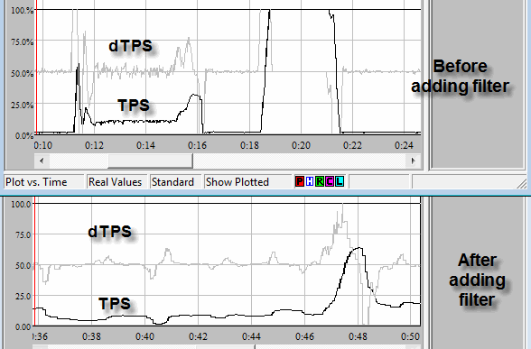
Just to throw this in there.
Before and after plots of TPS and TPSdot (AEM ECU).
I did the following:
- I totally hacked up my AEM's PCB layout/grounding and fixed newbie engineer boo-boos.
- Added a 2 pole filter to the TPS signal
The effect is much smoother throttle enrichment, most noticeably on very light throttle application at low RPM. The decel fuel cutoff also doesn't jerk in and out anymore on trailing throttle turns with very light throttle application. I was able to increase the sensitivity of throttle enrichment because there is far less noise to false trigger it. Off-idle throttle tip-in is noticeably crisper.