For instance-- the 'given' configuration that will definitely work: A single single coil, distributor based, even fire engined vehicle with an Optical, Hall or VR sensor (sensor doesn't really matter with v3 PCB anymore). As long as the CAS has an equal number of 'positions' to the number of cylinders that the vehicle has, and they are evenly spaced, then presto! No problems. For VR sensors this would be teeth on the wheel. For Opto or Hall sensors this would be slits or Windows.
So what about a CAS with 360 1 degree slits around it? That sounds like it should be easy enough to read... but does the MS-II code do so? What about MSnS_E? MS-I? (Most standard MS-I B&G fuel only code people would just trigger from the coil I suppose)
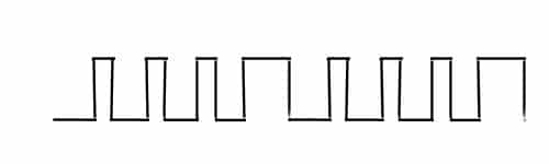
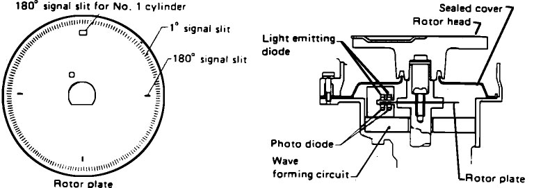
Here's a specific situation that motivated me to post this. The early 90's Nissan 240sx. Two optical sensors. Two rings of slits on the CAS wheel. The outer ring is 360 slits 1 degree apart. The inner ring has 4 slits 90 degrees apart (or 180 degrees of crank rotation apart since this wheel spins at cam speed which is half crank speed). I was just looking this over last night as I want to buy a project car for my new employee where he can use the stock ignition system and I feel pretty good about this but I have one minor hesitation…. The spacing of the inner 4 slits is right, but the No1 cyl slit is much wider than the rest, and still centered at 90 degrees it appears, meaning that the square wave will start sooner and end later than the other three. If it started at the same time as the other three and just ended later that may be fine as we could trigger from the rising edge and ignore when the pulse ended but I’m not sure about this arrangement as it appears the rising edge will start sooner.
What do you guys think? I'd love to see us turn out a resource of examples of supported configurations, illustrated. I can pulls pictures like this one of different CAS configurations to use as examples if needed.