Hi guys,
Is there anybody here who can help me with my problem. I have installed an Edis 8 system and MSII on my -73 Pontiac Firebird. When I tested the Edis system after mounted it (without MSand PIP/SAW connected), I didn't got any spark, so I tried to change the polarity on the VR sensor. But still no spark. Then I measured the voltage of the VR sensor while cranking, and I only got 1-1.5volt AC. On the Edis homepage it says 5-10volt while cranking.... I'm wondering what you guys get if you measure your VR Sensor while cranking.
Please help Swede who is desperate to start his Supercharged Firebird!!!!!
Thanks,
Anton
Edis VR Sensor voltage??
Moderators: jsmcortina, muythaibxr
-
jsmcortina
- Site Admin
- Posts: 39619
- Joined: Mon May 03, 2004 1:34 am
- Location: Birmingham, UK
- Contact:
What air gap do you have between sensor and trigger wheel ? Try reducing if possible to increase the voltage.
How quickly/slowly is the engine cranking ? If it is very slow then possibly the EDIS is not recognising the signal.
James
How quickly/slowly is the engine cranking ? If it is very slow then possibly the EDIS is not recognising the signal.
James
I can repair or upgrade Megasquirts in UK. http://www.jamesmurrayengineering.co.uk
My Success story: http://www.msextra.com/forums/viewtopic ... 04&t=34277
MSEXTRA documentation at: http://www.msextra.com/doc/index.html
New users, please read the "Forum Help Page".
My Success story: http://www.msextra.com/forums/viewtopic ... 04&t=34277
MSEXTRA documentation at: http://www.msextra.com/doc/index.html
New users, please read the "Forum Help Page".
I haven't measured the gap but it's less then 1mm. I don't know how fast the engine is cranking, it's an chevy small block with a tilton high torque mini starter. I have a friend who has an Volvo with Edis 4 and it starts as soon as you look at the ignition key...  We measured his VR Sensor output and it was 3-4volt AC.
But I need more input, please everybody, go out to your garage and measure your VR output, please!!!!
But I need more input, please everybody, go out to your garage and measure your VR output, please!!!!
According to the technical documentation here:
http://www.bgsoflex.com/mjl/mjl_edis_summary.html
the minimum voltage from the sensor is 0.5V. You should be fine. Double-check all the wiring connections. Check for rpm in MegaTune, if you MS box is connected. Failing that, you have a faulty module.
Roger.
http://www.bgsoflex.com/mjl/mjl_edis_summary.html
the minimum voltage from the sensor is 0.5V. You should be fine. Double-check all the wiring connections. Check for rpm in MegaTune, if you MS box is connected. Failing that, you have a faulty module.
Roger.
1979 Mazda RX-7, running MSnSExtra hi-res 09c for fuel and spark control on a turbocharged, intercooled, and (of course!) injected 13B rotary.

Which side/pin on this connector would you define as 1 (PIP) and which one is 12 (coil D)????? Can't you trust the notches on the schematic connector??PSIG wrote:It seems the most common error in EDIS wiring is that the schematic views are looking into the connectors on the wiring loom, not the module or coils. Maybe that helps?
-
jsmcortina
- Site Admin
- Posts: 39619
- Joined: Mon May 03, 2004 1:34 am
- Location: Birmingham, UK
- Contact:
I have just looked at the diagrams on the MS1/Extra site (taken from MegaJoltLite site) and I'm suprised to find that they are inconsistent with the connector in you hand - the detail of the notch and the guides at top and bottom of the connector do not match up.
You can often tell from the colours of the original wires and which ones are twisted together. This has always answered the question for me.
However, I will look at the EDIS looms I have at home later on and update this topic and my site to reflect what is correct. A picture of an EDIS module with the pins numbered would help too, so I'll try to do that too.
James
I can repair or upgrade Megasquirts in UK. http://www.jamesmurrayengineering.co.uk
My Success story: http://www.msextra.com/forums/viewtopic ... 04&t=34277
MSEXTRA documentation at: http://www.msextra.com/doc/index.html
New users, please read the "Forum Help Page".
My Success story: http://www.msextra.com/forums/viewtopic ... 04&t=34277
MSEXTRA documentation at: http://www.msextra.com/doc/index.html
New users, please read the "Forum Help Page".
-
jsmcortina
- Site Admin
- Posts: 39619
- Joined: Mon May 03, 2004 1:34 am
- Location: Birmingham, UK
- Contact:
If you could list the colours now we can probably figure it out.Qzmo wrote:That would be Super, James....
James
I can repair or upgrade Megasquirts in UK. http://www.jamesmurrayengineering.co.uk
My Success story: http://www.msextra.com/forums/viewtopic ... 04&t=34277
MSEXTRA documentation at: http://www.msextra.com/doc/index.html
New users, please read the "Forum Help Page".
My Success story: http://www.msextra.com/forums/viewtopic ... 04&t=34277
MSEXTRA documentation at: http://www.msextra.com/doc/index.html
New users, please read the "Forum Help Page".
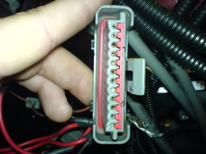
Here's the colors
I will list them as you see the connector on tht picture with number 1at the top of the connector and the plastic locking device on the right side.
It was very har to see the strip color but I hope that you can manage something out of it.
1 Beige/ Black stripe
2 Beige/ Blue stripe
3 Black/ White stripe
4 Beige/ Orange stripe
5 Beige/ White stripe
6 Orange/ Red Stripe
7 Red/brown something
8 Blue
9 White
10 Orange
11Beige something
12 Grey/ orange stripe
Hope you can help..
Last edited by Qzmo on Fri Jul 21, 2006 5:45 am, edited 1 time in total.
Here's the colors
I will list them as you see the connector on tht picture with number 1at the top of the connector and the plastic locking device on the right side.
It was very har to see the strip color but I hope that you can manage something out of it.
1 Beige/ Black stripe
2 Beige/ Blue stripe
3 Black/ White stripe
4 Beige/ Orange stripe
5 Beige/ White stripe
6 Orange/ Red Stripe
7 Red/brown something
8 Blue
9 White
10 Orange
11Beige something
12 Grey/ orange stripe
Hope you can help..
I will list them as you see the connector on tht picture with number 1at the top of the connector and the plastic locking device on the right side.
It was very har to see the strip color but I hope that you can manage something out of it.
1 Beige/ Black stripe
2 Beige/ Blue stripe
3 Black/ White stripe
4 Beige/ Orange stripe
5 Beige/ White stripe
6 Orange/ Red Stripe
7 Red/brown something
8 Blue
9 White
10 Orange
11Beige something
12 Grey/ orange stripe
Hope you can help..
-
jsmcortina
- Site Admin
- Posts: 39619
- Joined: Mon May 03, 2004 1:34 am
- Location: Birmingham, UK
- Contact:
I am pretty confident that the numbers are upside down so
1 Beige/ Black stripe 12 = coil D
2 Beige/ Blue stripe 11 = coil C
3 Black/ White stripe 10 = power ground
4 Beige/ Orange stripe 9 = coil B
5 Beige/ White stripe 8 = coil A
6 Orange/ Red Stripe 7 = signal shield
7 Red/brown something 6 = +12v supply
8 Blue 5 = VR+
9 White 4 = VR-
10 Orange 3 = SAW
11Beige something 2 = IDM
12 Grey/ orange stripe 1 = PIP
The giveaway is the four beige/stripe wires which are the coils.
James
I can repair or upgrade Megasquirts in UK. http://www.jamesmurrayengineering.co.uk
My Success story: http://www.msextra.com/forums/viewtopic ... 04&t=34277
MSEXTRA documentation at: http://www.msextra.com/doc/index.html
New users, please read the "Forum Help Page".
My Success story: http://www.msextra.com/forums/viewtopic ... 04&t=34277
MSEXTRA documentation at: http://www.msextra.com/doc/index.html
New users, please read the "Forum Help Page".

PSIG wrote:If it helps, here's a pic of an EDIS8 module where I'm trying to highlight where it is embossed with "PIN 1" next to the connector. Maybe others can check theirs to see if this is a standard feature. Note the wire colors are very similar - but different - than Qzmo's.
David
If I use Jsmcortina's list my cable 12 ends up by the embossed "pin 1", it's a bit hard to know what's right and what's wrong...
-
jsmcortina
- Site Admin
- Posts: 39619
- Joined: Mon May 03, 2004 1:34 am
- Location: Birmingham, UK
- Contact:
Maybe we got the numbers wrong? Whichever way I'm really confident that those beige wires are the coils
James
James
I can repair or upgrade Megasquirts in UK. http://www.jamesmurrayengineering.co.uk
My Success story: http://www.msextra.com/forums/viewtopic ... 04&t=34277
MSEXTRA documentation at: http://www.msextra.com/doc/index.html
New users, please read the "Forum Help Page".
My Success story: http://www.msextra.com/forums/viewtopic ... 04&t=34277
MSEXTRA documentation at: http://www.msextra.com/doc/index.html
New users, please read the "Forum Help Page".
-
jsmcortina
- Site Admin
- Posts: 39619
- Joined: Mon May 03, 2004 1:34 am
- Location: Birmingham, UK
- Contact:
I checked my EDIS8 and EDIS4 modules and the pin numbering is correct - pin1 matches pin1 in the diagrams and my list above is correct. PIP/SAW are by pin1 and the coils are at the other end. My EDIS8 colours are very similar to those above.
James
James
I can repair or upgrade Megasquirts in UK. http://www.jamesmurrayengineering.co.uk
My Success story: http://www.msextra.com/forums/viewtopic ... 04&t=34277
MSEXTRA documentation at: http://www.msextra.com/doc/index.html
New users, please read the "Forum Help Page".
My Success story: http://www.msextra.com/forums/viewtopic ... 04&t=34277
MSEXTRA documentation at: http://www.msextra.com/doc/index.html
New users, please read the "Forum Help Page".
As you say the colors match pretty well if I use your list. black/white= groundjsmcortina wrote:Maybe we got the numbers wrong? Whichever way I'm really confident that those beige wires are the coils
James
red=power 12+ the blue and the white to VR. I'm pretty sure that your list is ok. Is the schematics right then?? Mayby somebody just named one pin "pin 1" but instead it was "Pin 12".... I don't know. But what I can say is that if my module wasn't broken before it is that now..