Edis VR Sensor voltage??

A general forum and a place for initial or prospective users. See Manuals/Documentation
Click here to enter
Contact a Forum Administrator
If unsure where to post, post in this sub-forum.

Moderators: jsmcortina, muythaibxr

PSIG
Super MS/Extra'er
Posts: 1146
Joined: Sat Jun 12, 2004 12:02 am
Location: Seattle, WA area

Post by PSIG »

This would be funny if it wasn't so frustrating. :? Here's my angle - the schematics are correct as looking into the wiring loom connector.
Image
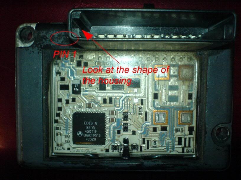
Using the retaining clip for reference on my EDIS8 on the shelf (F1AF-12K072-AC), LOOKING INTO THE MODULE (not the wiring) PIN 1 embossed on the module is next to PIP, PIN 6 is +12v power, PIN 10 is ground and everything else is relative.

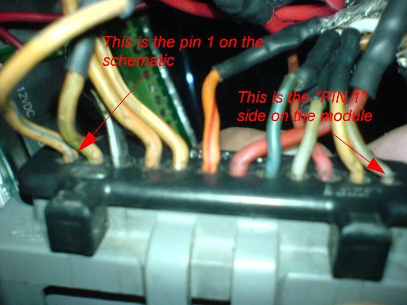
Once again, using the retaining clip as reference to the schematic and connector, this would mean Qzmo's picture
Image
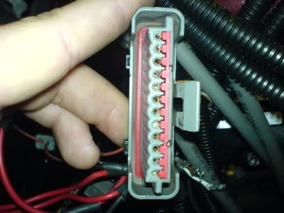
has the PIN 1 at the bottom how he is holding it. I would suggest ignoring wire colors as my PIP is beige/yellow and my PIN 12/coil D is grey/blue, although the power and ground are the expected red and black/grn and VR/PIP/SAW shielding is pink/red.

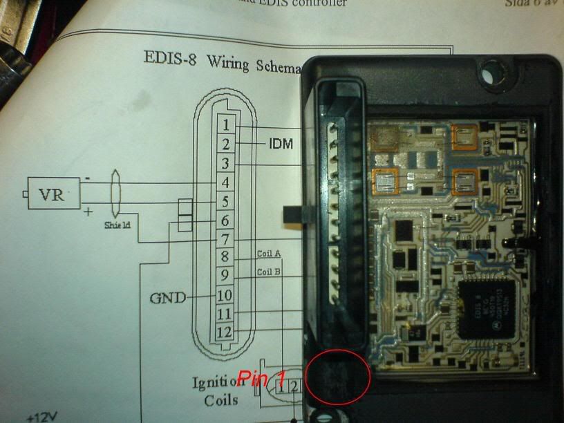
I would use the module's PIN1 and the retaining clip as a locating reference and show a module-view pinout for verification and possibly avoid some confusion. Perhaps I can get a better pic and try labeling it for the site.

David

PS - Qzmo, I could send you my spare EDIS8 at cost to get you going - PM me if you need it.
Qzmo
MS/Extra Newbie
Posts: 28
Joined: Thu Jul 20, 2006 8:05 am
Location: Umeå, Sweden

Post by Qzmo »

Ok guys,
Let's straighten this out once and for all... I will show some pictures of my module and connector.

Image
Here at the first picture you can see at my module and the embossed "PIN 1" and the shape of my connector. (I have taken of the lid on the module just to see if anything was burnt.)

Image
Here on the next picture you can all see the wiring on the connector, if I use Jsmcortina's list the colors match with the VR sensor and Power +12 and ground. But if I use the embossed "PIN 1" nothing matches.

Image
On this picture you can see a comparison between the schematic connector and the module housing. What i'm saying is that the shape of the schematic connector is designed wrong. The notches are switched. Am I wrong?? I mean that it dosen't matter how you look at the connector the notches are on the wrong side. Correct me if i'm wrong.....


Image
I really need this Edis ignition to work as you can see on this picture, I haven't got any space for a distributor.

Image
Once there was a distributor here......


Hope you all can understand my inferior English, but I try the best I can.
The pictures dosen't have the best quality, they are taken with my Ericsson phone......
jsmcortina
Site Admin
Posts: 39615
Joined: Mon May 03, 2004 1:34 am
Location: Birmingham, UK
Contact:

Post by jsmcortina »

PSIG wrote:This would be funny if it wasn't so frustrating. :? Here's my angle - the schematics are correct as looking into the wiring loom connector.
That's what the diagram says.

However, on further investigation I found some errors on those diagrams (that originally came from B&G's MegajoltLite site. The guide key details on the plugs are NOT the same as originally shown. The diagrams showed the keys for EDIS4 - the EDIS8 is opposite. I don't know about the EDIS6.

I have updated http://megasquirt.sourceforge.net/extra ... dware.html to be as clear as possible. Let me know if it makes sense now.

James
I can repair or upgrade Megasquirts in UK. http://www.jamesmurrayengineering.co.uk

My Success story: http://www.msextra.com/forums/viewtopic ... 04&t=34277
MSEXTRA documentation at: http://www.msextra.com/doc/index.html
New users, please read the "Forum Help Page".
jsmcortina
Site Admin
Posts: 39615
Joined: Mon May 03, 2004 1:34 am
Location: Birmingham, UK
Contact:

Post by jsmcortina »

Qzmo,
you are correct that the notches on the diagram WERE WRONG. I've fixed them now. You may need to hit refresh or CTRL-F5 or something to make you browser see the new picture.
The pin1 on the module IS CORRECT. That is PIP.

However the diagram does say "Note : Connectors are Shown Looking Into Wiring Harness" so laying the diagram beside the module is the wrong way up.

hope this helps

James
I can repair or upgrade Megasquirts in UK. http://www.jamesmurrayengineering.co.uk

My Success story: http://www.msextra.com/forums/viewtopic ... 04&t=34277
MSEXTRA documentation at: http://www.msextra.com/doc/index.html
New users, please read the "Forum Help Page".
Qzmo
MS/Extra Newbie
Posts: 28
Joined: Thu Jul 20, 2006 8:05 am
Location: Umeå, Sweden

Post by Qzmo »

jsmcortina wrote:
PSIG wrote:This would be funny if it wasn't so frustrating. :? Here's my angle - the schematics are correct as looking into the wiring loom connector.
That's what the diagram says.

However, on further investigation I found some errors on those diagrams (that originally came from B&G's MegajoltLite site. The guide key details on the plugs are NOT the same as originally shown. The diagrams showed the keys for EDIS4 - the EDIS8 is opposite. I don't know about the EDIS6.

I have updated http://megasquirt.sourceforge.net/extra ... dware.html to be as clear as possible. Let me know if it makes sense now.

James
Ok, so now I have wired the cables right but I still burned my module... :(
Life's a bitch and then you die. :(
Qzmo
MS/Extra Newbie
Posts: 28
Joined: Thu Jul 20, 2006 8:05 am
Location: Umeå, Sweden

Post by Qzmo »

jsmcortina wrote:Qzmo,

However the diagram does say "Note : Connectors are Shown Looking Into Wiring Harness" so laying the diagram beside the module is the wrong way up.
Yes i know i just wanted you all to see the faulty design of the guide key....
jsmcortina
Site Admin
Posts: 39615
Joined: Mon May 03, 2004 1:34 am
Location: Birmingham, UK
Contact:

Post by jsmcortina »

Looking inside the EDIS8 module you can see the four power transistors that drive the coils at the opposite end to pin1. This confirms that pin1 is correct because the coils are around pin12.

James
I can repair or upgrade Megasquirts in UK. http://www.jamesmurrayengineering.co.uk

My Success story: http://www.msextra.com/forums/viewtopic ... 04&t=34277
MSEXTRA documentation at: http://www.msextra.com/doc/index.html
New users, please read the "Forum Help Page".
Qzmo
MS/Extra Newbie
Posts: 28
Joined: Thu Jul 20, 2006 8:05 am
Location: Umeå, Sweden

Post by Qzmo »

jsmcortina wrote:Looking inside the EDIS8 module you can see the four power transistors that drive the coils at the opposite end to pin1. This confirms that pin1 is correct because the coils are around pin12.

James
Exactly!! You were right the whole time. But what happend to my module when I corrected my wiring???
1973 Pontiac Firebird, Chevrolet 355, Opcon Twinscrew Supercharger, Megasquirt II, Edis 8 (working):) , Tex Racing manual transmission, Frankland Quickchange rearend.
jsmcortina
Site Admin
Posts: 39615
Joined: Mon May 03, 2004 1:34 am
Location: Birmingham, UK
Contact:

Post by jsmcortina »

Well, it would appear that you have connected -12v to the SAW input. This could easily have broken the module, but you never know.

Now it is wired correctly, try swapping the VR sensor wires again - just in case. You can leave the Megasquirt disconnected as it is not required for the EDIS to spark.

James
I can repair or upgrade Megasquirts in UK. http://www.jamesmurrayengineering.co.uk

My Success story: http://www.msextra.com/forums/viewtopic ... 04&t=34277
MSEXTRA documentation at: http://www.msextra.com/doc/index.html
New users, please read the "Forum Help Page".
Post Reply