MS3 Wasted Spark & Sequential Vapour LPG

A general forum and a place for initial or prospective users. See Manuals/Documentation
Click here to enter
Contact a Forum Administrator
If unsure where to post, post in this sub-forum.

Moderators: jsmcortina, muythaibxr

Post Reply
stirlsilver
Helpful MS/Extra'er
Posts: 38
Joined: Sat Jun 29, 2013 5:29 am

MS3 Wasted Spark & Sequential Vapour LPG

Post by stirlsilver »

Hello everyone,
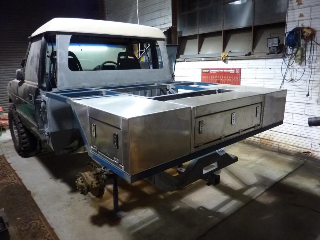
I'm currently in the process of building a Discovery Ute, and below is where I am currently at:
Image

Image

Anyway, the car will be powered by a Twin Turbo Land Rover 3.9L engine with 8:1CR on LPG only. As the subject suggests, I intend to use MS3 to control the ignition in wasted spark mode and the fuel sequentially.

I'm in the process of desiging the wiring and circuitry to make it all happen, I've found heaps of information for the configuration of the crank signal, cam signal, coolant, air temp etc. But I haven't found any information at all on running the vapour LPG injection system (the injectors and the needed sensors). What I do know is this:
*LPG injectors are low impedance and need the Peak & Hold Circuit Board
*To correctly meter the fuel the pressure and temperature in the LPG fuel rail needs to be known
*MS3 natively supports LPG injection

What I am struggling with is:
*What sensors or kits have people used to get MS3 to run vapour LPG injection?
*How are the sensors wired to MS3?
*How is MS3 configured to use the sensor data in adjusting the fuel metering?

Can anyone provide me with some information here? I have never used a MS ecu before so i'm trying to get my head around it all.

Thanks,
Stirling
stirlsilver
Helpful MS/Extra'er
Posts: 38
Joined: Sat Jun 29, 2013 5:29 am

Re: MS3 Wasted Spark & Sequential Vapour LPG

Post by stirlsilver »

Is anyone able to help out? Or at least provide some pointers?
billr
Super MS/Extra'er
Posts: 6828
Joined: Sun May 15, 2011 11:41 am
Location: Walnut Creek, Calif. USA

Re: MS3 Wasted Spark & Sequential Vapour LPG

Post by billr »

Okay, I don't have any LPG experience, so was keeping quiet; but maybe I can help you get a discussion going. Most sensors, like MAP, TPS, ECT, CKP, etc. will be the same with any fuel. I presume you are referring to sensors that relate to determining the mass-flow rate of the injectors, so that req_fuel can be calculated just the same as any other fuel. I know there are some older threads here that relate to LPG (or maybe CNG?), do some searching over the last couple of year's postings. Those injectors are different from common gasoline/alcohol ones, look for info from the injector manufacturers. Also look for info relating to LPG carb conversions, those have been going on for many, many years and there should be a lot of info available regarding LPG stoic ratios, heat content of the liquid, etc.
DaveEFI
Super MS/Extra'er
Posts: 4175
Joined: Sun Apr 15, 2012 12:55 am
Location: SW London, UK

Re: MS3 Wasted Spark & Sequential Vapour LPG

Post by DaveEFI »

stirlsilver wrote:Is anyone able to help out? Or at least provide some pointers?
I'd ask if you really need to go sequential. I'm running a RV8 3.5 on petrol using low impedance injectors driven directly from a V3 - but batch obviously.
Rover SD1 3.5 EFI
MS2 V3
EDIS
Tech Edge O2
London UK.
Marek
Master MS/Extra'er
Posts: 576
Joined: Sun May 10, 2009 1:20 am
Location: Guildford UK

Re: MS3 Wasted Spark & Sequential Vapour LPG

Post by Marek »

Dear Stirling,

*What sensors or kits have people used to get MS3 to run vapour LPG injection?
*How are the sensors wired to MS3?
*How is MS3 configured to use the sensor data in adjusting the fuel metering?

Aftermarket kits from the lpg world are typically not of much use here because they work by monitoring the petrol injector pulsewidth once the engine is sufficiently warmed up and feed the result to a second ECU which intercepts this, cuts off the petrol signal and feeds a correspondingly adjusted signal to an lpg injector instead. As you have already noticed, MS can do this itself directly with the added ability to start and warmup on lpg.

One typical way to do this is via relays:- the injector 12v can be first fed to a changeover relay so power only goes to the petrol or the lpg injectors. If there is any common wiring between the two injector fuel types, you may find that some of the petrol or lpg injectors will be of an indeterminate state, as they are usually of sufficiently low impedance to provide a potential path to earth for the 12v. Peak and hold is one way to drive low impedance injectors but lpg injectors don't necessarily follow the 4:1 peak:hold ratio that all petrol injectors do, so creative thinking is needed when going this route, in particular to heat dissipation. This is because lpg injectors tend to have longer dead times and lower impedances, so the driver electronics are "on" for longer, perhaps delivering higher currents than in the equivalent petrol scenario. Another way to drive two sets of injectors is to run one bank on the mainboard and the other on MS3X. It is also possible to intercept the signal to pins 2 and 4 of mainboard U4 and run twin sets of injectors that way.

The only new sensors to consider would be a combined pressure and temperature sensor for the gas and a temperature sensor for the reducer. Bosch make a combined part suitable for the former (it is used by Prins) - part number 0281 002 456. (I have one spare for sale and can let you have calibration details.)

Pressure/temperature calibration is just part of tuning and MS3 supports gas pressure/temperature adjustment, as well as alternative afterstart and warmup curves. The lpg reducer is a self adjusting system in the same way that a conventional petrol pump is - it will constantly leak gas into the manifold to maintain a near constant pressure versus MAP. It doesn't know what to do about the temperature that that fuel is at, but the temperature variation is conveniently inversely proportional to that of air temperature. The same potential pressure/temperature mismatch exists at startup with the calorific value of the cranking pulse width also being slightly different for a hot restart compared to a cold start, but these are minor issues in the general scheme of things.

The sensor on the reducer is used only to switch back to petrol if the reducer ices up. You'd want to also arrange similar for the lpg tank sender.

kind regards
Marek
stirlsilver
Helpful MS/Extra'er
Posts: 38
Joined: Sat Jun 29, 2013 5:29 am

Re: MS3 Wasted Spark & Sequential Vapour LPG

Post by stirlsilver »

Hi Marek,
Thank you very much for you post! This is the sort of information I am looking for.

I am definitely trying to avoid the aftermarket kit with the intercepting module, for the exact reason that they default to starting on petron injectors to warm up the engine, and then switch to LPG. I don't have any petrol injectors. The car doesn't even have a petrol tank anymore. So there is no need for me to have an ability to control two types of injectors from MS.

I appreciate the information on the Bosch T-MAP sensor, if I can't find one here in Australia, I may take up your offer on the one you have. I'll also first need to check to see if it is easy enough to fit the sensor onto the injector manifold rail. I would imagine that these sensors simply connect to some of the general purpose analogue inputs on the MSX connector and these inputs are then selected in the MS software?

I'm also a little confused by this statement "temperature variation is conveniently inversely proportional to that of air temperature", can you please clarify on this point?

I'm curious to know, have you found it hard to start and run an engine with the system cold? I did read some posts that mentioned the engine ran rough when cold.

Again, thanks
Stirling
Marek
Master MS/Extra'er
Posts: 576
Joined: Sun May 10, 2009 1:20 am
Location: Guildford UK

Re: MS3 Wasted Spark & Sequential Vapour LPG

Post by Marek »

Cold lpg gas is denser than hot lpg gas, so contains more fuel per cc injected. You need a lower injection time (all things being equal) for cold lpg, i.e. at startup than you do for a fully warmed up engine. The same but to a smaller degree will be true when not stuck in traffic and underbonnet temperatures vary.

Cold air is denser than hot air. You'll notice from the air correction curve supplied with MS that with "more air" per cc injected, you'll need more fuel to keep the air:fuel ratio the same than at higher air temperatures.

The engine may well run a little more roughly when cold as it is difficult to tune:- the amount of fuel can be varied (reduced) at low temperatures using an inverse warmup enrichment curve (WUE2) and also via the pressure/temperature correction curves, so getting the mix right isn't a simple matter. I don't pretend that my engine is properly tuned yet, so can't definitively report back.

The Bosch sensor I mentioned has a recommended conditioning circuit which you'd have to build on the proto area. The Bosch website in Australia has details downloadable as a pdf document.

I am not aware of what the legal requirements for any of this will be in your part of the world. It'll certainly be different than in the UK and other parts of europe where lpg is more popular. Whilst the regulations permitting one to offer defined lpg parts for sale is common in the EU, the fitting and/or modification of lpg varies from country to country.

kind regards
Marek
stirlsilver
Helpful MS/Extra'er
Posts: 38
Joined: Sat Jun 29, 2013 5:29 am

Re: MS3 Wasted Spark & Sequential Vapour LPG

Post by stirlsilver »

Hello everyone,
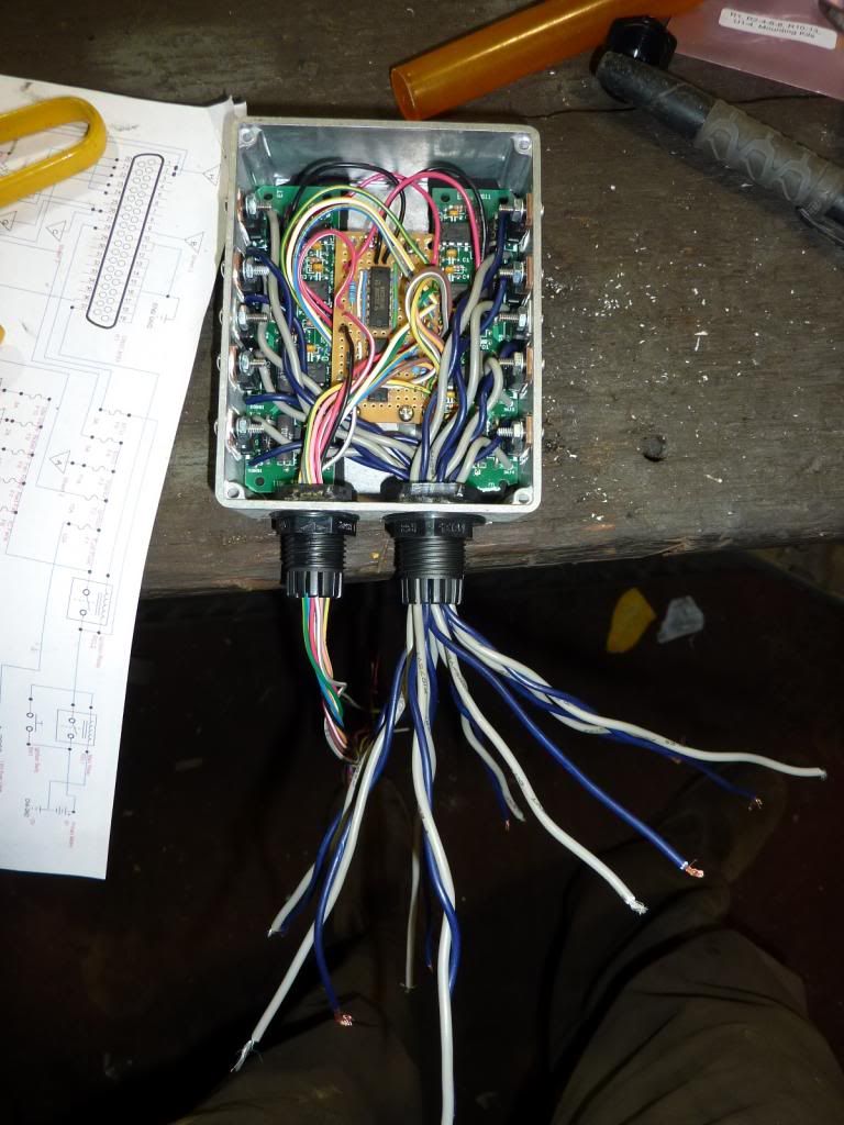
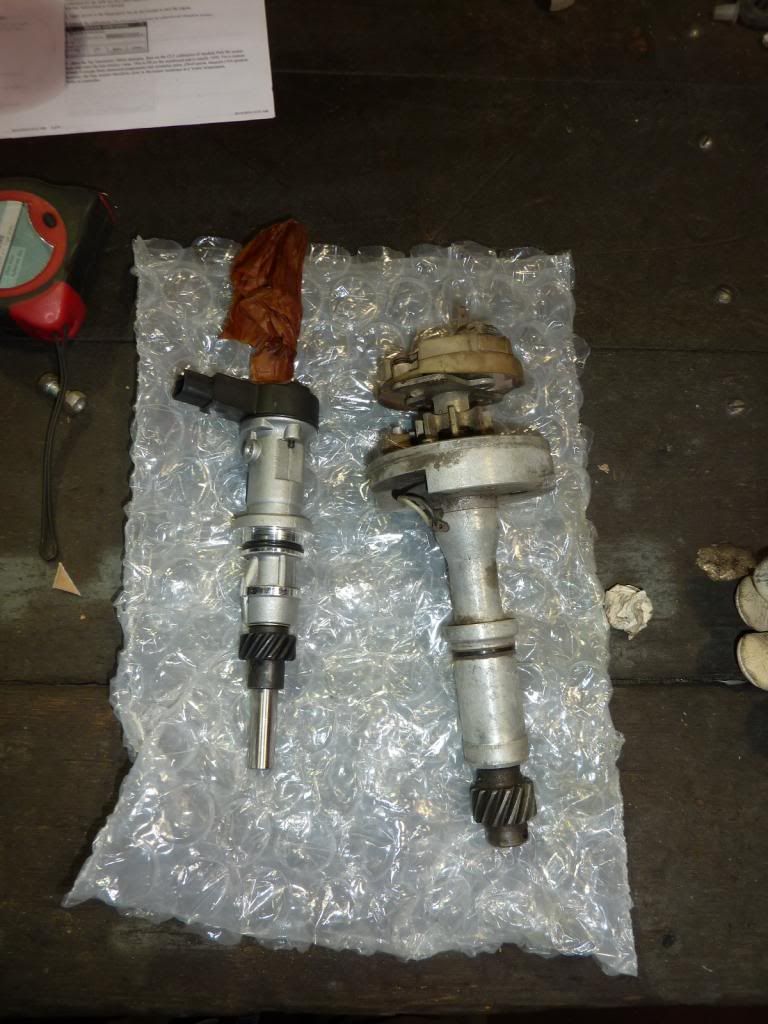
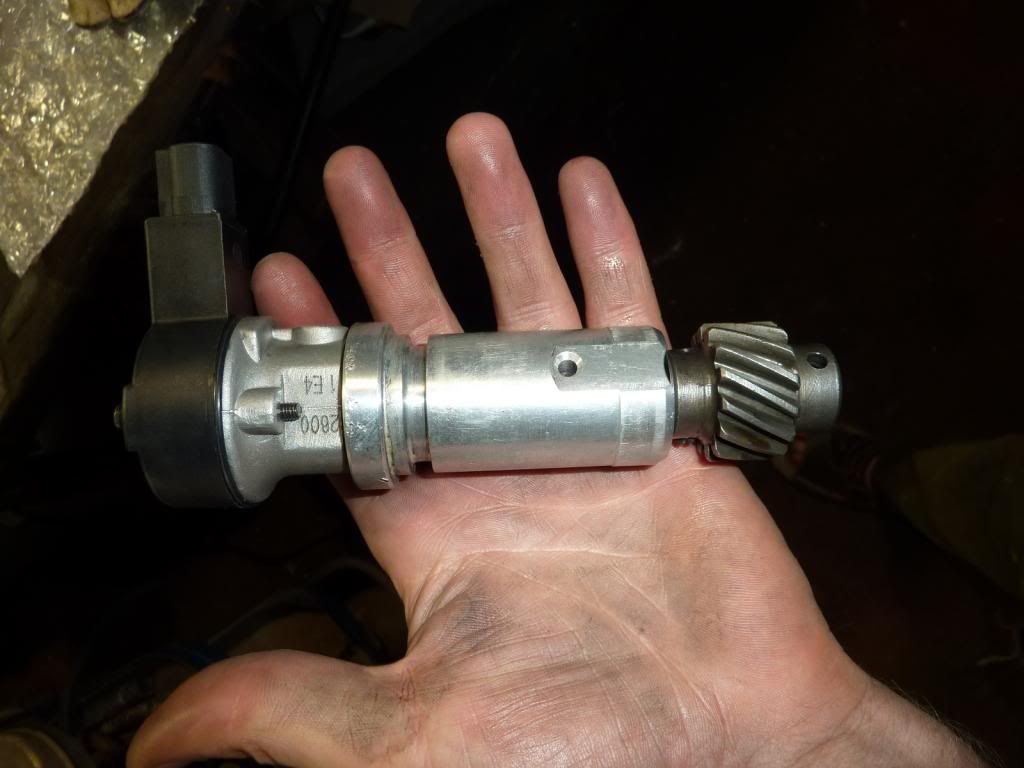
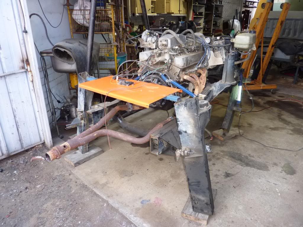
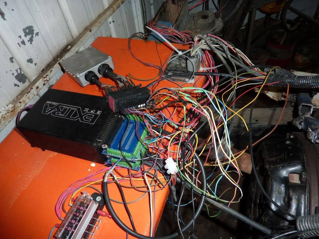
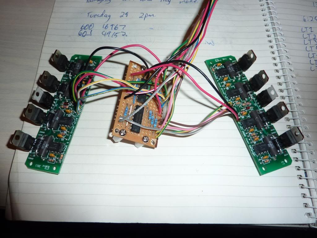
It has been some time since my last post, but I am slowly working my way through this project. I now have essentially the whole system wired up onto an engine on a test stand so that I can work through all the issues while I have good access to the engine. Here are a few shots:

The peak & hold board
Image
Image

The converted distributor into a cam position sensor:
Image
Image

The test engine:
Image
Image

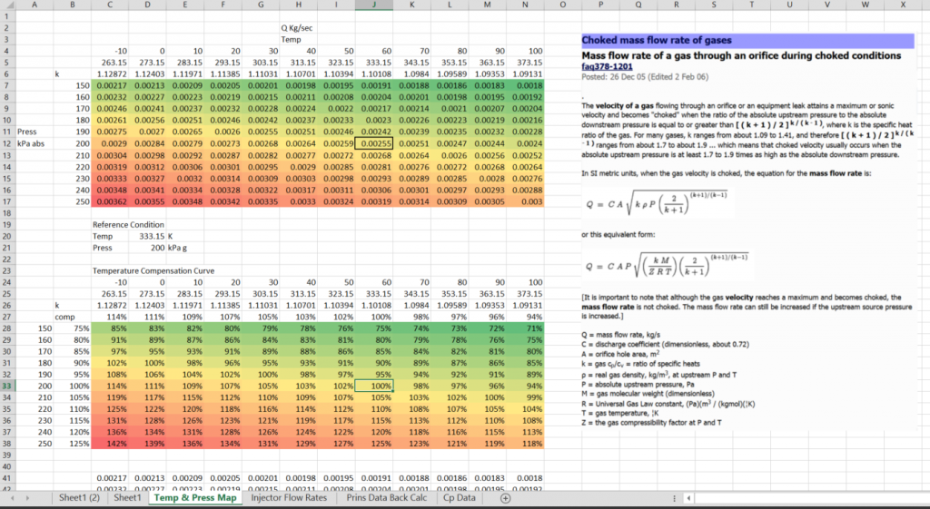
Anyway, I have been doing research into how to do the fueling compensation for the temperature & pressure of the LPG fuel rail and I think I now have all the calculations sorted for the Keihin injectors:
Image

According to the data I have obtained, the flow through the injectors is governed by the choked flow effect. What essentially it means is that the flow rate through the injector is only governed by the pressure in the LPG fuel rail rather than the difference between the fuel rail pressure and manifold pressure (it sounds bizzare but it's true http://en.wikipedia.org/wiki/Choked_flow). Anyway I have a problem which I hope someone can help me with. I read the Megasquirt-3: TunerStudio MS Lite Reference Guide and in section 9.18 it says:
the pressure used for the lookup is always pressure across the injector i.e. rail pressure - intake pressure

How can I change the lookup pressure to be the rail pressure only??
Post Reply